System and method for engine lubrication

Inactive Publication Date: 2008-12-25
CRR DEV
View PDF3 Cites 6 Cited by
  • Summary
  • Abstract
  • Description
  • Claims
  • Application Information

AI Technical Summary

Benefits of technology

[0008]An object of the present invention is to overcome or alleviate one or more limitations of the prior art and/or provid

Problems solved by technology

Coal mine gas has produced many lethal explosions in coal mines.
Unfortunately, many waste gases such as methane are relatively ‘dry’ fuels that can result in significant wear and deterioration of engine parts.
However, in waste gas fuelled engines, the waste gases generally do not provide significant lubrication to prevent wear on the engine components such as valve stems and piston cylinder walls.
Methane-powered engines also suffer from an abrasive cryst

Method used


Image

  • System and method for engine lubrication
  • System and method for engine lubrication
  • System and method for engine lubrication

Examples


Embodiment Construction

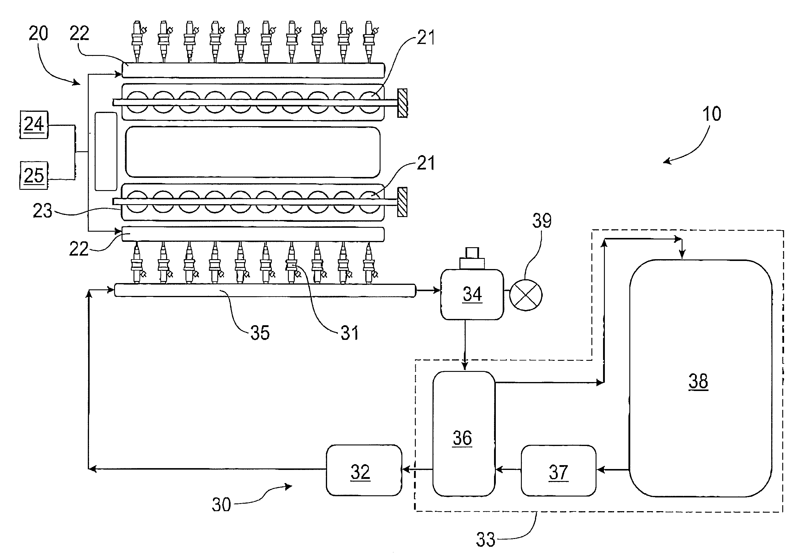
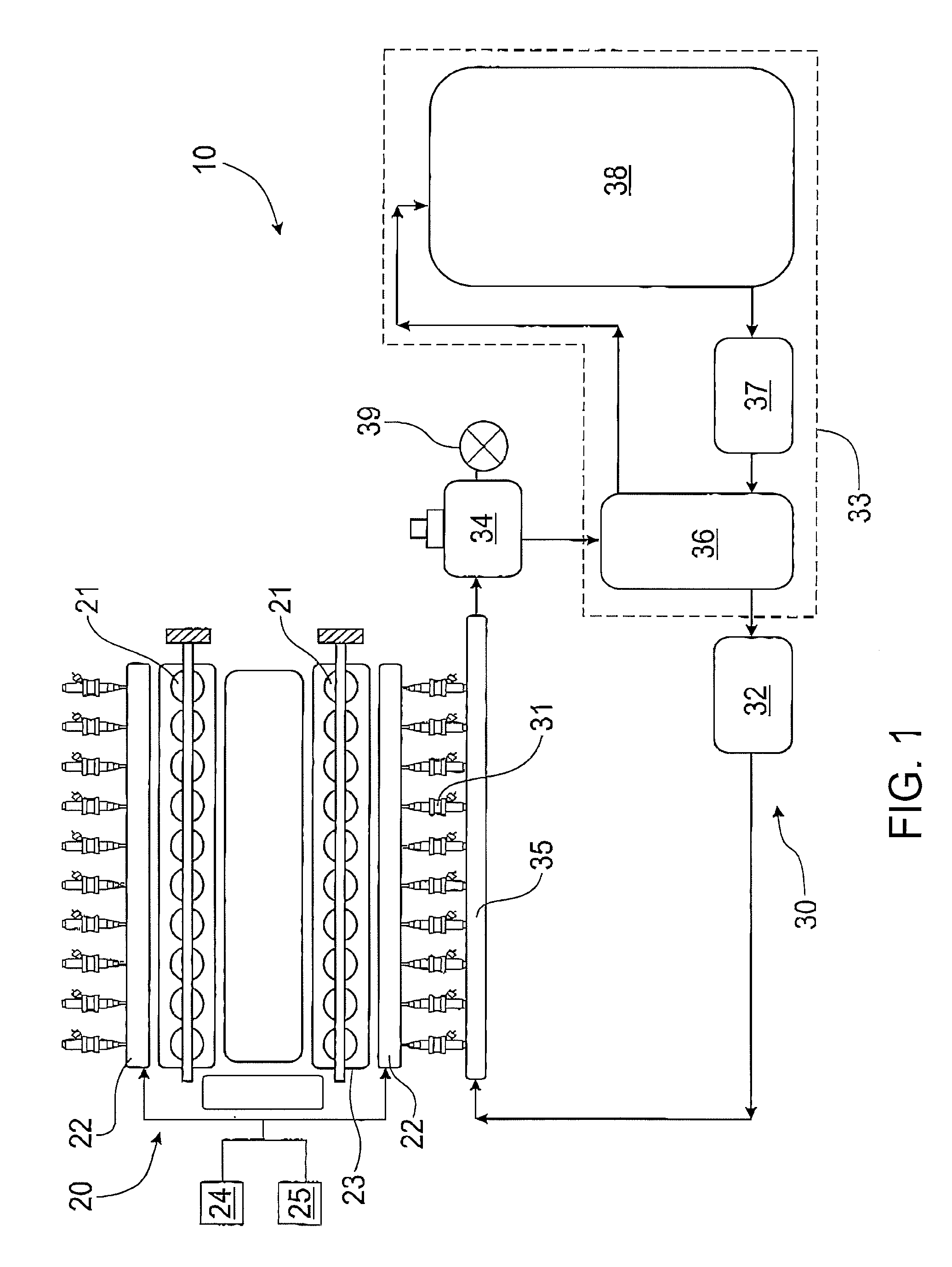
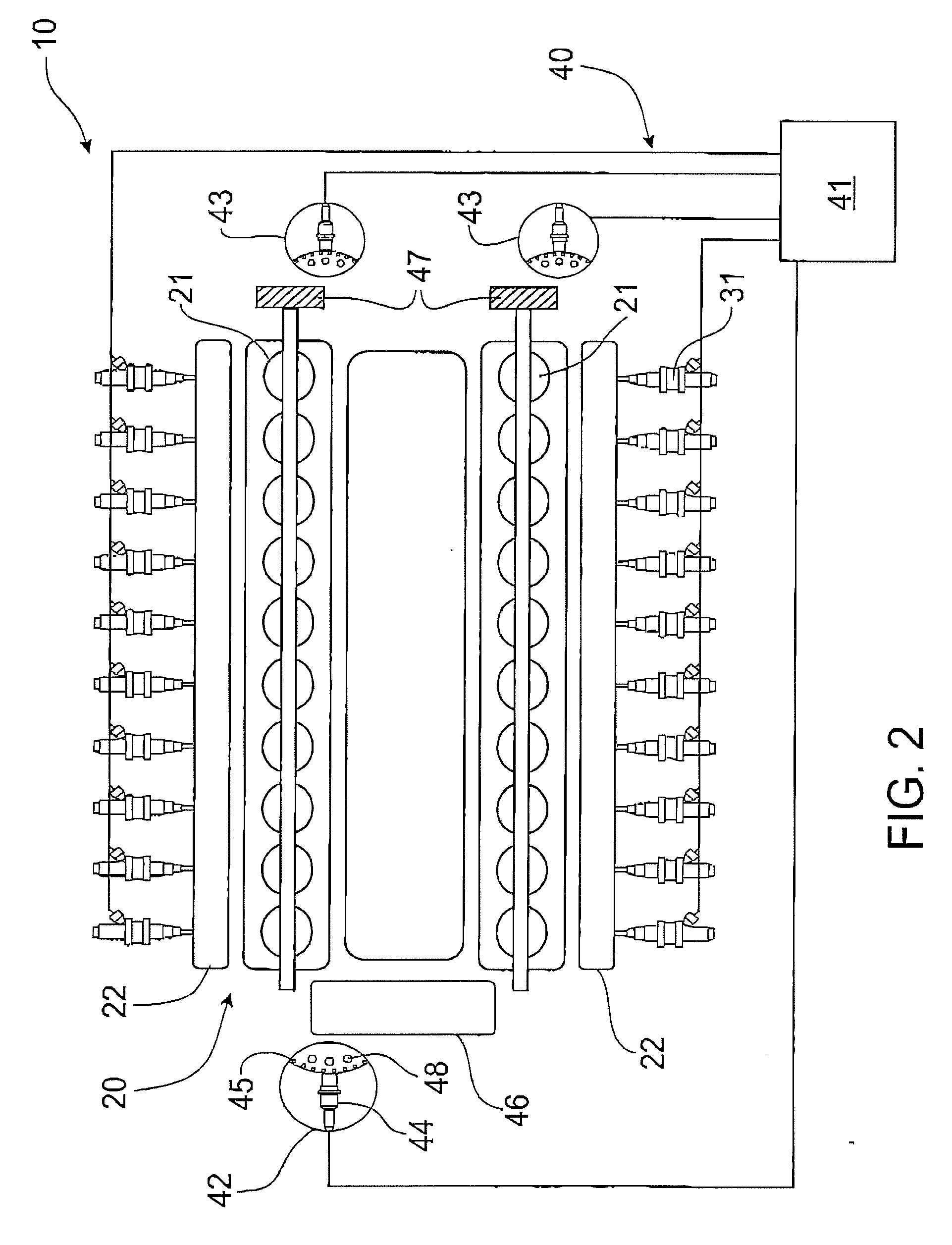
[0030]FIGS. 1 and 2 show a liquid phase lubricant system 10 retrofitted to an existing stationary 20-cylinder diesel V-engine 20 that has been converted to using methane gas.

[0031]The engine 20 includes two rows of cylinders 21. Each cylinder 21 is operatively connected to an intake manifold 22. An air intake system 23 and a gaseous phase fuel delivery system 24 is operatively connected to each cylinder 21 via the intake manifold 22, as known in the prior art.

[0032]The liquid phase lubricant system 10 includes a lubricant delivery system 30 and a lubricant control system 40. Although the invention is explained with reference to stationary engines, the inventor envisages that the invention is also applicable in other environments such as vehicle engines running on similar ‘dry’ fuels.

[0033]FIG. 1 shows the lubricant delivery system 30 which delivers a 10-weight mineral oil to each cylinder 21 of the engine 20. However, it is to be appreciated that other forms of lubricant may be used...


PUM


Abstract

The invention resides in an internal combustion engine (20) comprising an air intake system (24) operatively connected to a cylinder (21), a gaseous phase fuel delivery system (25) operatively connected to the cylinder (21), and a liquid phase lubricant injection system (10) operatively connected to the cylinder (21). An atomised portion of liquid phase lubricant is injected into a mixture of gaseous phase fuel and air by the liquid phase lubricant injection system (10) to lubricate components of the cylinder (21) prior to burning the mixture in the cylinder (21).

Description

FIELD OF THE INVENTION[0001]The present invention relates to lubrication of internal combustion engines. In particular, although not exclusively, the invention relates to a system and method for lubricating engine cylinder walls using lubricant injectors.BACKGROUND TO THE INVENTION[0002]Flammable gas is considered a waste bi-product of many industrial processes. For example, coal mine gas (commonly known as firedamp) consists primarily of highly flammable methane that is produced during the geochemical process of carbonizing organic material into coal. Coal mine gas has produced many lethal explosions in coal mines. Therefore, coal mines today are generally elaborately and carefully ventilated to ensure that explosive concentrations of coal mine gas are removed. However, rather than simply venting coal mine gas directly to the atmosphere as pollution, coal mine gas is sometimes captured and used as a fuel to run engines that can perform useful work at a mine site. For example, large...

Claims


Application Information

Patent Timeline
IPC IPC(8): F01M1/04
CPCF01M1/08F01M1/14F01M3/04
Inventor ROMANO, ROBERTROMANO, CHRISTOPHER
Owner CRR DEV
Why Eureka
Try Eureka