
Power Semiconductor Module And Method of Manufacturing the Power Semiconductor Module

a technology of power semiconductor modules and semiconductor modules, which is applied in the direction of semiconductor devices, semiconductor device details, electrical apparatus, etc., can solve the problems of increasing reliability, reducing the size and cost of inverters, and reducing the size and cost of electric power conversion systems, so as to reduce the size and cost, improve cooling performance, and reduce thermal resistance

Inactive Publication Date: 2008-12-25
HITACHI LTD
View PDF9 Cites 26 Cited by
  • Summary
  • Abstract
  • Description
  • Claims
  • Application Information

AI Technical Summary

Benefits of technology

[0006]Recent electric power converting (inverting) systems in which a power module is mounted are required to be reduced in size and cost and have high reliability. For examples, major problems with automobiles are to reduce the size and cost of an electric power converting system in which a power module is mounted and to increase the reliability of the system. That is, requirements for automobiles are to reduce effects on the earth environment and increase gas mileage. To satisfy these requirements, widespread use of vehicle driving mechanisms or motor pre-driver that electrically operate is essential. Accordingly, ease of mounting an inverter on a vehicle must be improved and the cost of the inverter must be reduced. Major problems with automobiles are then to reduce the size and cost of the inverter and increase its reliability.
[0009]An object of the present invention is to provide a power semiconductor module cooling performance of which is increased by reducing a thermal resistance between the semiconductor chip and a heat dissipating mechanism as well as an inverter system, an electric power converting system, and a vehicle-mounted electric system in which the power semiconductor module is used to reduce their size and cost and to increase their reliability.
[0017]The structure described above reduces the thermal resistance between the semiconductor chip and the heat dissipating mechanism and thereby improves the cooling performance. It also becomes possible to reduce the sizes and costs of an electric power converting system and a vehicle-mounted electric system and to increase their reliability.
[0018]The present invention can provide a power semiconductor module for which cooling performance can be improved by reducing a thermal resistance between a semiconductor chip and a heat dissipating mechanism.
[0019]It is also possible to reduce the sizes and costs of an inverter and a vehicle-mounted electric system and to increase their reliability.

Problems solved by technology

For examples, major problems with automobiles are to reduce the size and cost of an electric power converting system in which a power module is mounted and to increase the reliability of the system.
Major problems with automobiles are then to reduce the size and cost of the inverter and increase its reliability.
However, when this type of power semiconductor module is mounted on an HEV, it is problematic in that heat dissipation sufficient as a power module is not achieved.
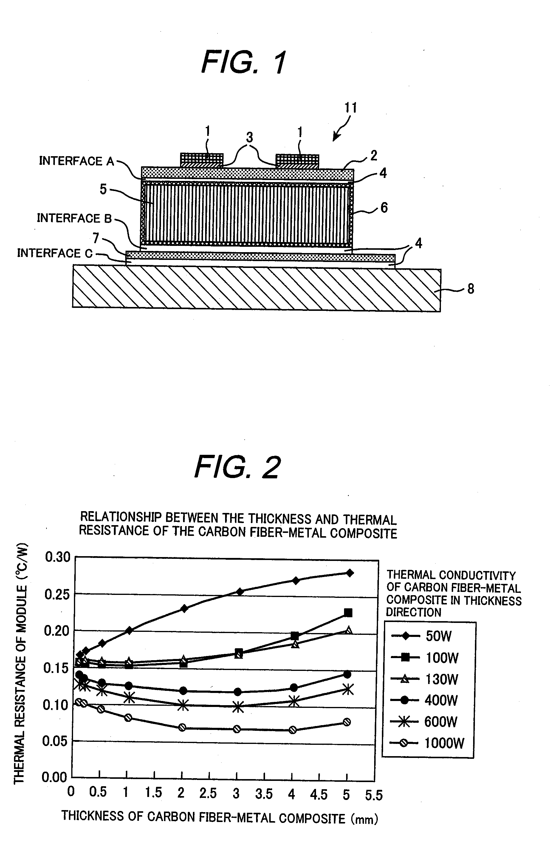
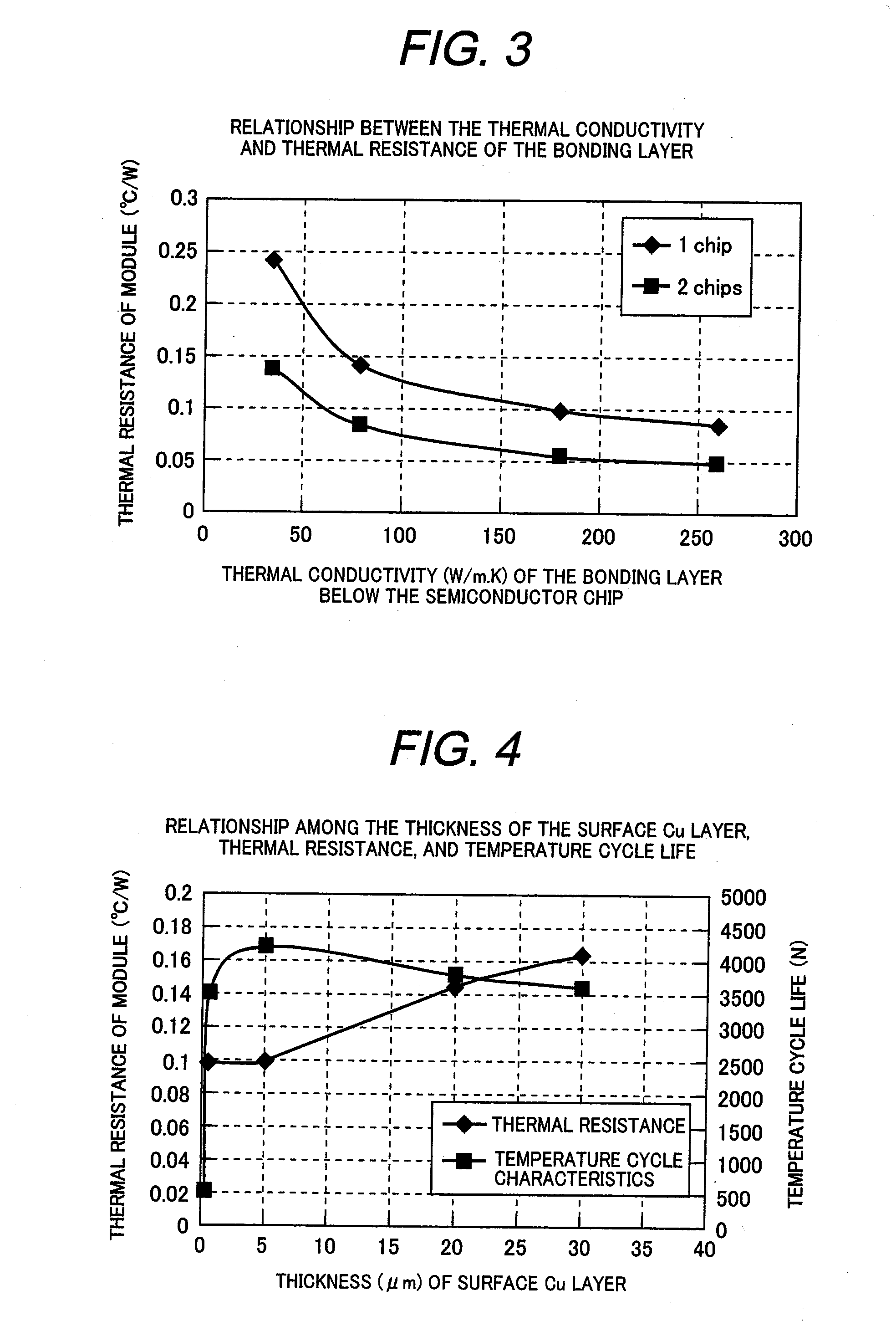
Accordingly, it is difficult to reduce the thermal resistance Rj-w to 0.15° C. / W or less as required for power modules mounted HEVs of the above type.

Method used


Image

  • Power Semiconductor Module And Method of Manufacturing the Power Semiconductor Module
  • Power Semiconductor Module And Method of Manufacturing the Power Semiconductor Module
  • Power Semiconductor Module And Method of Manufacturing the Power Semiconductor Module

Examples


Embodiment Construction

[0030]Embodiments of the present invention will be described with reference to the drawings.

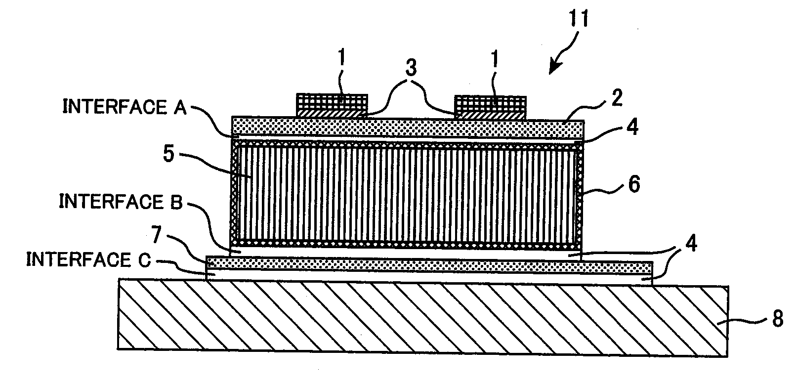
[0031]In the embodiments described below, a vehicle-mounted inverter, which undergoes severe thermal cycles and operates in a server operation environment, will be used as an example to describe a power semiconductor module according to the present invention and an inverter in which the power semiconductor module is mounted. The vehicle-mounted inverter is disposed in a vehicle-mounted electric system as a controller for controlling the driving of a vehicle-mounted motor. To control the driving of the vehicle-mounted motor, the inverter receives DC electric power from a vehicle-mounted battery, which is a vehicle-mounted power supply, converts the received DC electric power to prescribed AC electric power, and supplies the resulting AC electric power to the vehicle-mounted motor.

[0032]The structure described below can also be applied to a power module that constitutes an electric power conver...


PUM


Abstract

A power semiconductor module has a silicon nitride insulated substrate, a metal circuit plate made of Cu or a Cu alloy, which is disposed on one surface of the silicon nitride insulated substrate, a semiconductor chip mounted on the metal circuit plate, and a heat dissipating plate made of Cu or a Cu alloy, which is disposed on the other surface of the silicon nitride insulated substrate; a carbon fiber-metal composite made of carbon fiber and Cu or a Cu alloy is provided between the silicon nitride insulated substrate and the metal circuit plate; the thermal conductivity of the carbon fiber-metal composite in a direction in which carbon fiber of the carbon fiber-metal composite is oriented is 400 W / m·k or more. Accordingly, a power semiconductor module that has a low thermal resistance between the semiconductor chip and a heat dissipating mechanism and also has improved cooling capacity is provided.

Description

CLAIM OF PRIORITY[0001]The present application claims priority from Japanese patent application serial No. 2007-165748, filed on Jun. 25, 2007, the content of which is hereby incorporated by reference into this application.FIELD OF THE INVENTION[0002]The present invention relates to a power semiconductor module and a method of manufacturing the power semiconductor module.BACKGROUND OF THE INVENTION[0003]Semiconductor devices, particularly power semiconductor devices that control switching of high current, generate much heat. To ensure that these power semiconductor devices operate stably, cooling structures with superior cooling efficiency have been considered. Performance required to cool a power semiconductor device depends on the environment of the electric system in which the electric circuit module including the power semiconductor module is mounted. For example, an inverter mounted on an automobile requires high cooling performance due to a mounting environment and operation e...

Claims


Application Information

Patent Timeline
IPC IPC(8): H01L23/36H01L21/58
CPCH01L23/3735H01L24/45H01L24/48H01L24/49H01L24/83H01L25/072H01L2224/45015H01L2224/45124H01L2224/48091H01L2224/48137H01L2224/49109H01L2224/73265H01L2224/83801H01L2924/01005H01L2924/01013H01L2924/01014H01L2924/01027H01L2924/01029H01L2924/01047H01L2924/01049H01L2924/0105H01L2924/01074H01L2924/01078H01L2924/01082H01L2924/13055H01L2924/13091H01L2924/16195H01L2924/19041H01L2924/19107H01L2924/2076H01L2224/32225H01L2924/01006H01L2924/01019H01L2924/01023H01L2924/01033H01L2924/014H01L2924/0132H01L2924/0133H01L2224/92247H01L2924/0134H01L24/29H01L24/32H01L2224/45147H01L2224/29111H01L2924/01028H01L2924/1306H01L2924/1305H01L2924/00014H01L2924/01022H01L2924/3512H01L2924/00H01L2924/00012H01L2924/00011H01L2224/83205
Inventor IMAMURA, HISAYUKIMORITA, TOSHIAKIHOUZOUJI, HIROSHI
Owner HITACHI LTD
Learn More