Microphone Having an Output Signal Amplifier

a technology of output signal and amplifier, which is applied in the field of microphones, can solve the problems of poor signal-to-noise ratio, very weak output signal of condenser microphone, and very susceptible to interference of signal transmission from the microphone to an external microphone preamplifier, so as to reduce the susceptibility of interference of the microphone, improve the signal-to-noise ratio, and improve the effect of signal output level

Inactive Publication Date: 2008-12-25
ROBERT BOSCH GMBH
View PDF7 Cites 10 Cited by
  • Summary
  • Abstract
  • Description
  • Claims
  • Application Information

AI Technical Summary

Benefits of technology

[0009]It is an object of the present invention to describe a microphone that can be operated with less susceptibility to interference.
[0010]An example microphone according to the present invention, having a microphone housing with a microphone capsule, the microphone being connected via a microphone cable to an audio system, has an integrated amplifier that raises the signal output level.
[0011]The integration of a preamplifier into the microphone advantageously reduces the microphone's susceptibility to interference. In contrast to conventional preamplifiers, the preamplifier does not, or not exclusively, operate as an impedance converter, but instead amplifies the output voltage. As a consequence, the signal-to-noise ratio is advantageously increased even in the presence of interference. The preamplifier can be provided with energy via a battery or accumulator mounted in the microphone, or advantageously from the audio system via additional conductors in the microphone cable.

Problems solved by technology

A disadvantage of condenser microphones is their very weak output signal, with a typical signal output level from 0.5 mV RMS to 2 mV RMS.
Because of this very low signal level, signal transmission from the microphone to an external microphone preamplifier is very susceptible to interference.
For utilization, for example, in a tour bus, the multifarious interference signals together with microphone cable lengths of several meters thus lead to a poor signal-to-noise ratio and therefore to clearly audible interference during microphone announcements.
In specific cases, this interference cannot be eliminated even by laborious shielding measures.
A disadvantage of this downstream placement of the amplifier, however, is that the interference noise that is introduced is thereby also amplified.

Method used


Image

  • Microphone Having an Output Signal Amplifier
  • Microphone Having an Output Signal Amplifier

Examples


Embodiment Construction

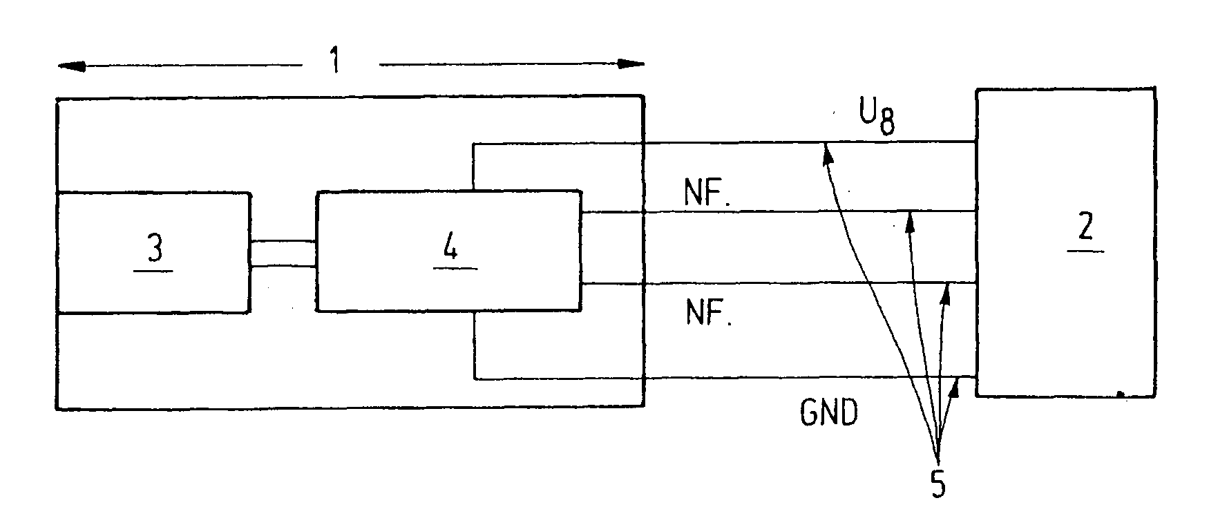
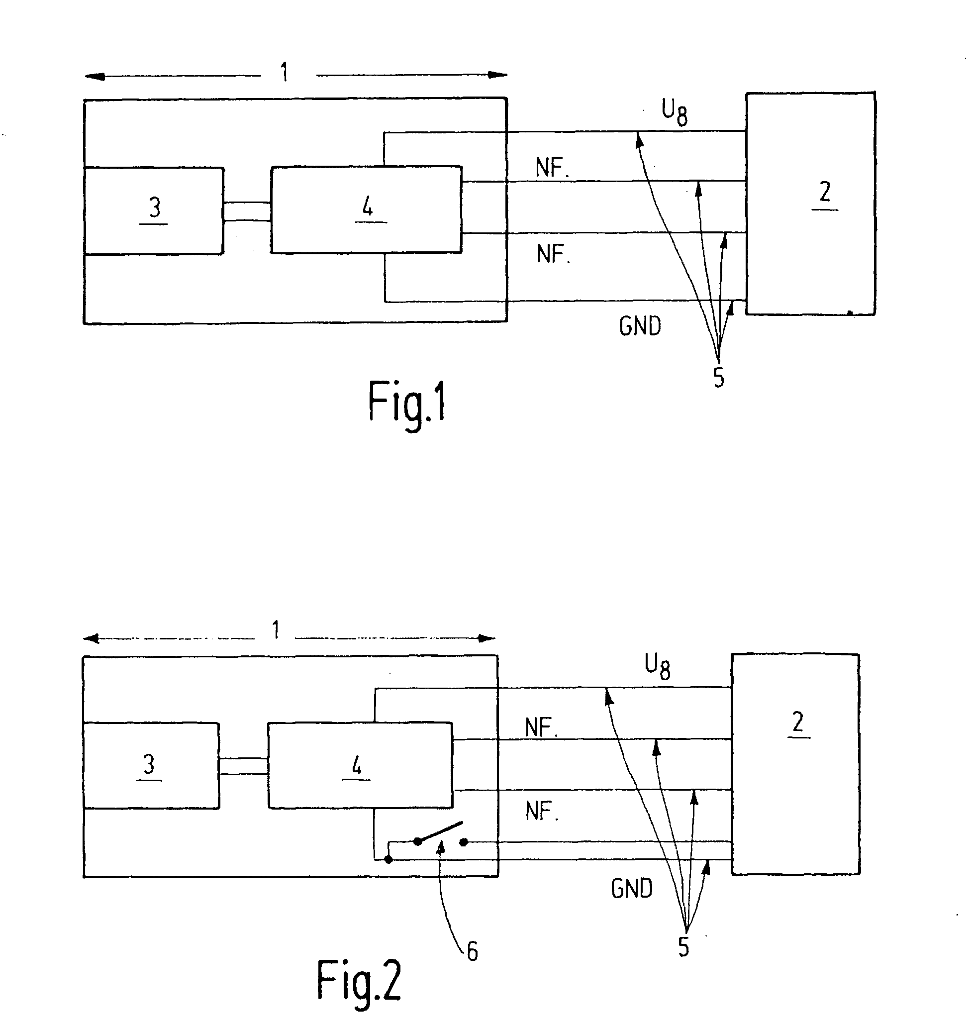
[0019]In condenser microphones, the mechanical oscillations of the membrane is converted into electrical oscillations. The so-called low-frequency technique has proven successful for conversion. In the low-frequency circuit, the microphone capsule is charged via a resistor to a fixed DC voltage. This can be between 40 V and 200 V. When an acoustic wave strikes the membrane, the capacitance of the condenser changes in the same rhythm as the acoustic waves, as a function of the spacing of the condenser plates. This results in a charge equalization and thus in a corresponding AC voltage at the resistor. The voltage drop at the resistor is proportional to the magnitude of the change in capacitance and the magnitude of the applied DC voltage. For a condenser capacitance of 20 pF to 100 pF (depending on microphone type), the resistor must have a value between 80 MΩ and 400 MΩ. A long electrical lead cannot be connected to such a high-resistance source. When a signal source has, for exampl...


PUM


Abstract

A microphone is described including a microphone housing having a microphone capsule disposed therein. The microphone is connected via a microphone cable to an audio system, and has an integrated amplifier that raises the signal output level. The integration of a preamplifier into the microphone advantageously reduces the microphone's susceptibility to interference. In contrast to conventional preamplifiers, the preamplifier does not, or not exclusively, operate as an impedance converter, but instead amplifies the output voltage. As a consequence, the signal-to-noise ratio is advantageously increased even in the presence of interference. The preamplifier can be provided with energy via a battery or accumulator mounted in the microphone, or advantageously from the audio system via additional conductors in the microphone cable.

Description

FIELD OF THE INVENTION[0001]The present invention relates to a microphone.BACKGROUND INFORMATION[0002]A microphone receives, via a membrane, acoustic oscillations in the form of acoustic pressure or an acoustic pressure difference, and converts them into electrical voltage signals. Different categories of microphones are known, such as passive dynamic microphones and condenser microphones, e.g., active electret condenser microphones.[0003]Dynamic microphones, in terms of their operation, utilize the induction law to convert a membrane motion into a change in voltage. The plunger coil microphone is common today. The membrane responds to atmospheric oscillations and guides an electrical conductor through a strong magnetic field. In the conductor, a voltage is induced that behaves proportionally to the speed at which the membrane moves. Dynamic microphones do not require a supply voltage, are robust, and operate with low distortion even at high volumes. Because of the substantially lar...

Claims


Application Information

Patent Timeline
Patent Type & Authority Applications(United States)
IPC IPC(8): H04R3/00
CPCH04R3/06H04R2410/00
Inventor SCHLICHTING, JENS
Owner ROBERT BOSCH GMBH
Why Eureka
Try Eureka