
Communication Device with Structural Part

a communication device and structural technology, applied in the direction of behind the ear hearing aids, deaf-aid sets, electric devices, etc., can solve the problems of difficult and expensive shape, limited maximum output, and high cost of hearing aid casings, so as to reduce overall size of hearing aids and thin walls

Inactive Publication Date: 2008-12-25
OTICON
View PDF2 Cites 10 Cited by
  • Summary
  • Abstract
  • Description
  • Claims
  • Application Information

AI Technical Summary

Benefits of technology

[0005]It is an object of the present invention to provide a communication device with casing parts, which are particularly well suited for avoiding the feed back problems of prior art communication devices and whereby the structural parts are easily shaped to form complex parts and whereby also the material has a high heat resistance.
[0006]The object of the invention is achieved with a communication device according to claim 1. By using a fibre-rich polymer material it is assured, that the feed-back problem are alleviated because the resonance frequency of the shell is raised to a much higher frequency than in a conventional polymer shell. This means that the vibration insulation of the rubber suspension will be much more effective and that the described shell vibrations leading to acoustical and mechanical feedback will be much reduced. Also the high fibre content of the material ensures elevated heat resistance, such that it becomes possible to perform solder operations in metal parts which are embedded in the material.
[0007]In an embodiment of the invention the reinforced polymer is a poluarylamide-based compound. This material has the advantage, that in injection moulding it may be caused to produce a surface layer with low fibre content, and thereby the surface quality of the moulded part will be close to the quality obtainable with materials with no fibre reinforcement. Even with a very high fibre contents this material may be caused to produce high quality surfaces. Also thin walled parts are producible with high fibre contents using this material. Thus this material is especially well suited for hearing aid and similar communication parts, where typically complex shapes must be moulded, and where further the demands to the surface appearance are very high.
[0010]When the E-module of the reinforced polymer material used is above 19 MPa it becomes possible to produce hearing aid shells which are considerably thinner than usual and at the same time ensures that acoustic energy is not easily transferred from the receiver suspension and into the shell material. This is because the acoustic impedance of the shell material at suspension points should differ as much as possible from the acoustic impedance of the suspension material. This is ensured according to the invention by using a very stiff reinforced polymer material as shell part and a very flexible suspension part. Further it should be noted that the thin walls facilitated by the high E-module is an important advantage, as this allows the overall size of the hearing aid to be minimized.
[0011]In a further embodiment of the invention a receiver enclosure is provided which has wall parts forming part of the casing which in cooperation with detachable wall parts form the enclosure in an air tight manner for sound isolation of the receiver. Such a sound tight isolation of the receiver with respect to the rest of the device allows the use of a vented receiver. A receiver of this type has an orifice, which radiates sound into the enclosure, but due to the sound tightness of the enclosure this will have no effect on the microphones which are also inside the casing. When the material used for the enclosure has the added stiffness as provided by the fibre-reinforcement, the sound radiated from the receiver enclosure can be kept at a minimum value even with a very thin walled structure. Added sound isolation is preferably achieved by providing a flexible packing or gasket means between the wall part of the casing and the detachable wall part.
[0012]In an embodiment the casing comprises a first and a second part which are tightly joined along respective edge lines whereby a flexible packing or gasket material is provided in the edge line between the two casing parts. Such a packing material helps to ensure a sound tight joint between the first and the second part of the casing. Thereby it is ensured, that the rigid parts of the casing will join in a manner which provides maximum security against penetration of detrimental substances such as humidity, sweat or dust.

Problems solved by technology

These efforts have to some degree solved the problem, but there still are limitations to the maximum output tolerated by apparatuses of this kind, before feed back problems occur.
It is further known to produce casing parts for hearing aids in titanium, but this material is difficult and expensive to shape, and thus the resulting hearing aid casing will be very expensive.
Heat resistance up to 270° Celsius is desired, and it is not easy to achieve with usual polymer materials.

Method used


Image

  • Communication Device with Structural Part
  • Communication Device with Structural Part
  • Communication Device with Structural Part

Examples


Embodiment Construction

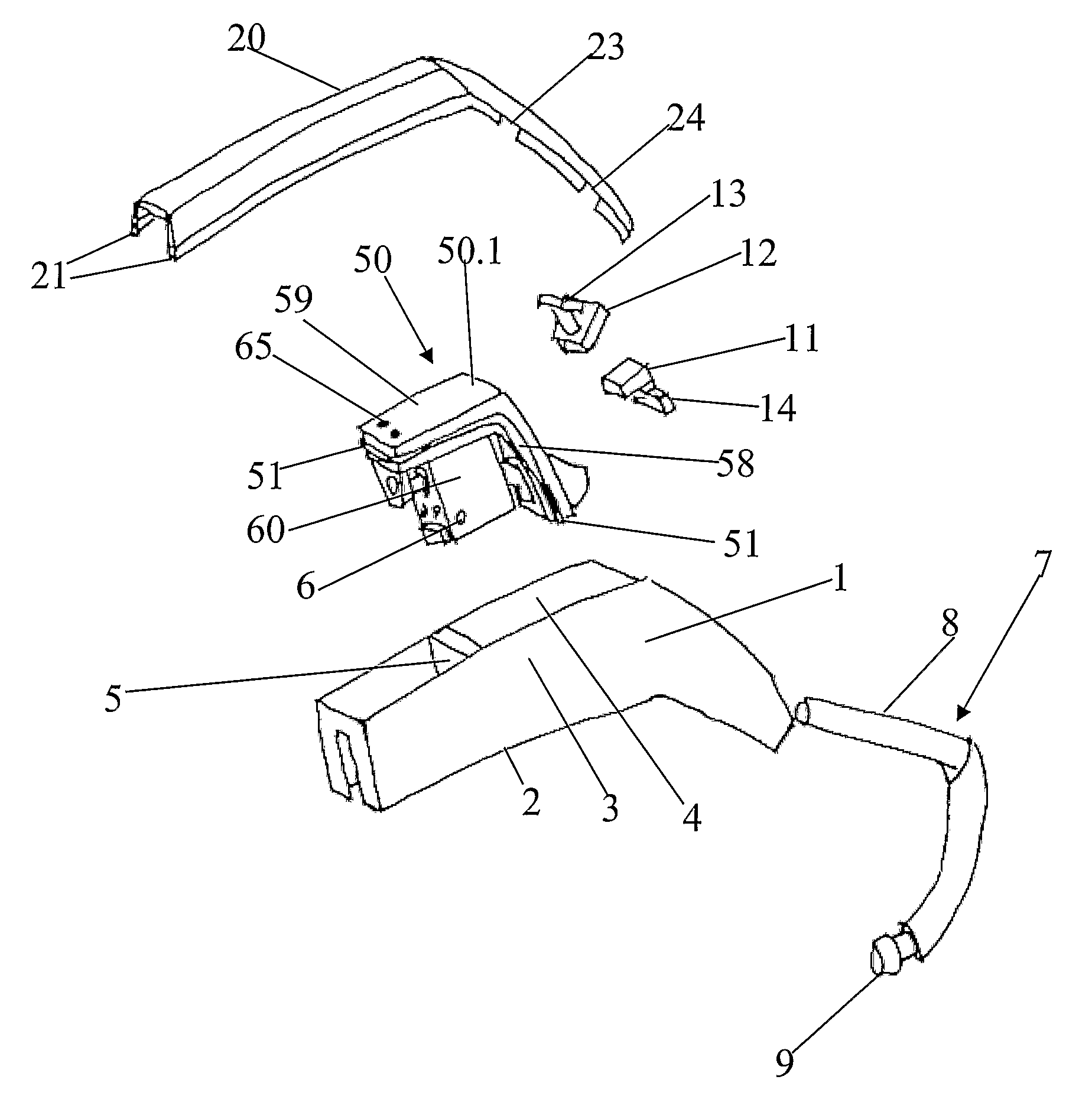
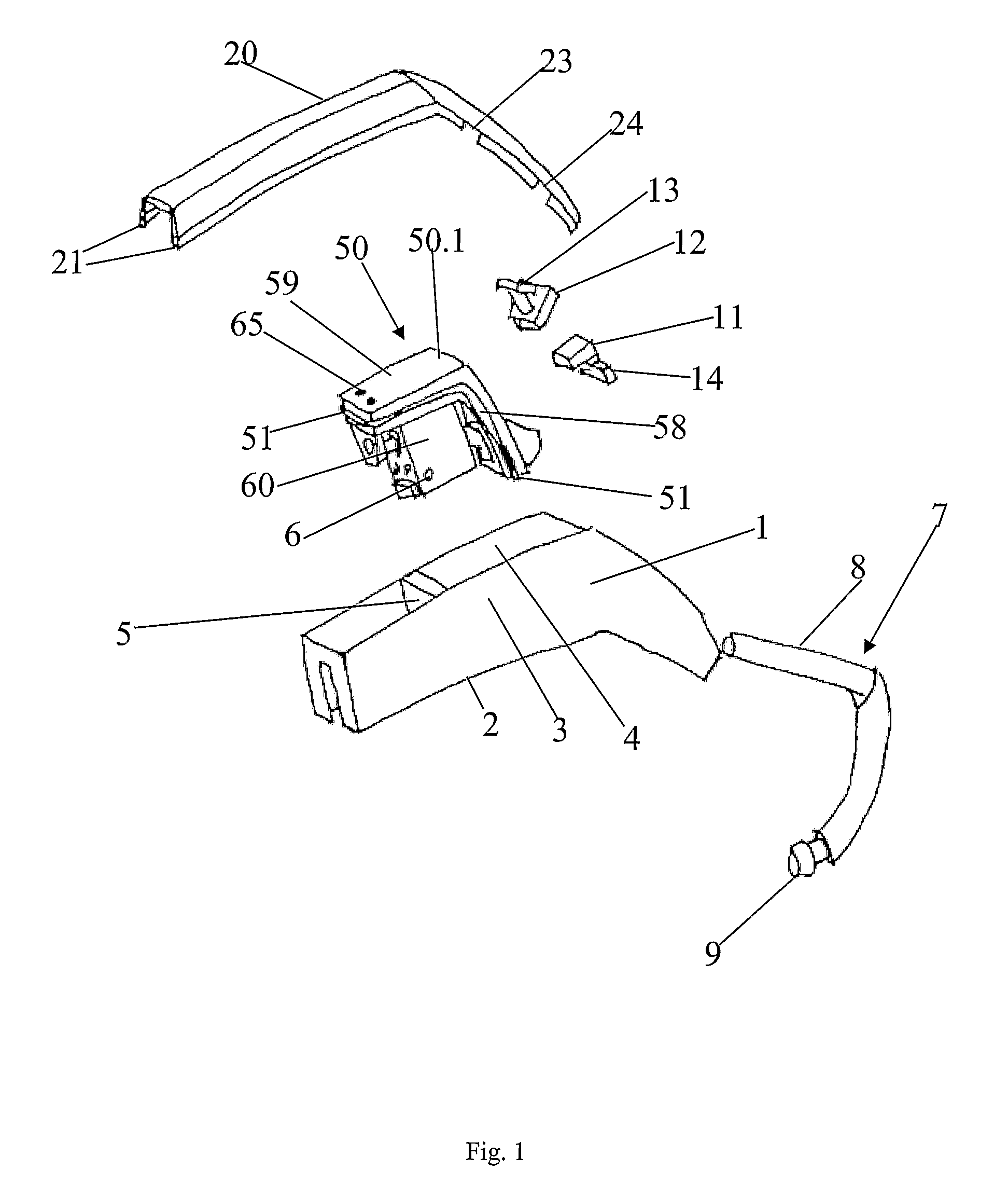
[0016]The exploded view of FIG. 1 displays the various parts of the hearing aid. The hearing aid comprises a bottom shell 1 and a top shell 20. When assembled the bottom shell 1 and the top shell 20 encloses a receiver assembly 50 and the microphones 11, 12. A hook 7 is insertable into the bottom shell 1 in order to provide a sound guide from the receiver 60 to the surroundings.

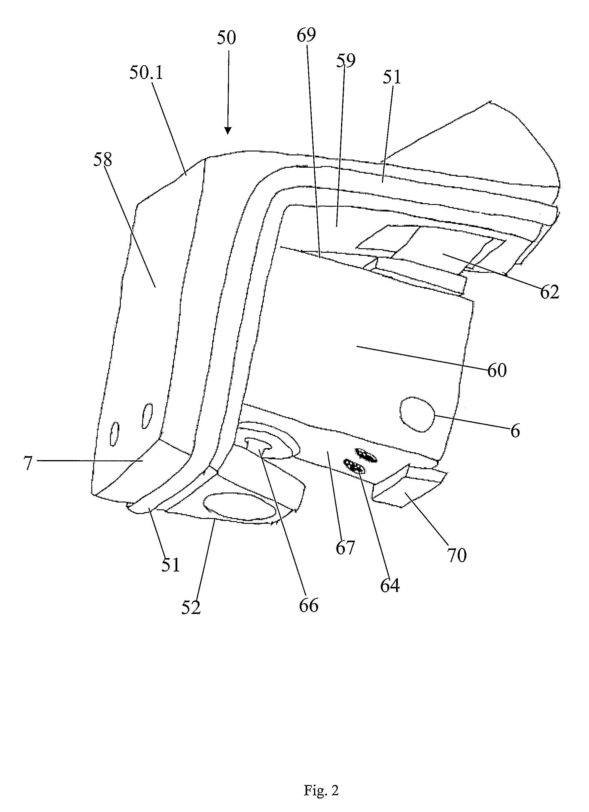
[0017]The receiver assembly 50 is described in more detail with respect to FIGS. 2 and 3. The receiver 60 has a sound outlet opening (not visible) in a first side and a flexible tube part 62 is coupled to the sound opening. The flexible tube 62 is shaped along with a tube 63 in order to form a combined sound outlet duct and receiver suspension part. At a side 67 the receiver has connection terminals 64 and also a further flexible suspension pole 66 is arranged at this side. The receiver assembly in FIG. 2 comprises the receiver 60 with suspensions 66, 62 and a receiver enclosure cover 50.1. This cover 50.1 ha...


PUM


Abstract

The invention concerns a communication device with casing parts enclosing a microphone and a receiver and suspension points therefore in the casing. A sound canal from the receiver to the ear of a user is provided, and the casing parts are shaped from an injection moulded fibre-reinforced polymer.

Description

AREA OF THE INVENTION[0001]The invention relates to a communication device with a structural part like a hearing aid or a headset. In such devices both a microphone and a receiver are provided and typically within the same casing. The receiver is provided for reproducing and presenting the audio signal picked up by the microphone to the user. Especially in hearing aids the microphone and the receiver are often placed in each others vicinity, and this may lead to serious feed back problems. When the structural parts of the device carries the audio signal from the receiver to the microphone serious limitations on the maximum output sound pressure from the receiver may be the result.BACKGROUND OF THE INVENTION[0002]In hearing aids and other communication devises this problem has been dealt with in a number of ways. Firstly soft parts have been used as suspension for both receiver and microphone. Further it has been tried to enclose the receiver in an enclosure separated from the microp...

Claims


Application Information

Patent Timeline
IPC IPC(8): H04R25/00
CPCH04R25/604H04R25/658H04R2225/021H04R25/607
Inventor TIPSMARK, CLAUSSVENDSEN, KLAUS L.LUNDBY, JENS
Owner OTICON
Learn More