
Sealant for ink jet head, ink jet head, and ink jet recording apparatus

a technology of ink jet and sealing portion, which is applied in the direction of coating, printing, instruments, etc., can solve the problems of defective electric connection, ink penetration into the inner electrode connection portion, and ink leakage, and achieve high reliability

Inactive Publication Date: 2008-12-25
CANON KK
View PDF18 Cites 2 Cited by
  • Summary
  • Abstract
  • Description
  • Claims
  • Application Information

AI Technical Summary

Benefits of technology

[0015]The present invention provides an ink jet head having high reliability.
[0017]Therefore, it is possible to provide a sealant or an adhesive for an ink jet head which can be cured at a low temperature and which can maintain high bonding reliability and high sealing reliability in a severe environment in which it contacts an ink containing alkali and polar solvents.
[0018]Although it is generally necessary to thickly apply a sealant in view of electric sealability, the sealant for an ink jet head of the present invention can be thinly applied. Therefore, for example, in the surface electrode configuration, the paper distance can be decreased to improve print quality. In addition, in the back electrode configuration, even when the thickness of a sealant to an ink is small, high bonding reliability and high sealing reliability can be achieved, and coating accuracy in a micro region can be relaxed, thereby improving productivity.
[0019]These effects enable the production of an ink jet head having high reliability at low cost.

Problems solved by technology

Since the landing accuracy during ink discharge improves as the distance (paper distance) from the recording paper decreases, a configuration including a thinned sealant has the large problem of securing electric sealing reliability in order to improve print quality.
Further, in the use of a recording head, a recording medium or the like may come into contact with a sealing portion due to paper jam.
The solder functioning as the fluid boundary is corroded with some kinds of ink to form a space in the ring, thereby causing ink penetration into an inner electrode connection portion and an ink leakage.
Further, the corrosion of the electric connection may cause defective electric connection.
Alternatively, because the bonding area is narrow, the sealant may be scraped due to a reduction in adhesive force, thereby causing a short-circuit.
For the above-mentioned reasons, it is very difficult to maintain adhesiveness and electric sealing reliability.
However, the sealant disclosed in Japanese Patent Laid-Open No. 2002-208652 is applied to general electronic devices, and thus the performance in such a severe environment that the sealant contacts an ink is not described.
A sealant or adhesive used for an ink jet head contains alkali and polar solvents and has the large problem of maintaining the characteristics described below in a severe environment in which it contacts an ink exhibiting properties which change with color.
Further, an ink jet head with the surface electrode configuration or back electrode configuration has a large problem with bonding reliability and electric sealing reliability in a thinned state required for a sealing material.

Method used


Image

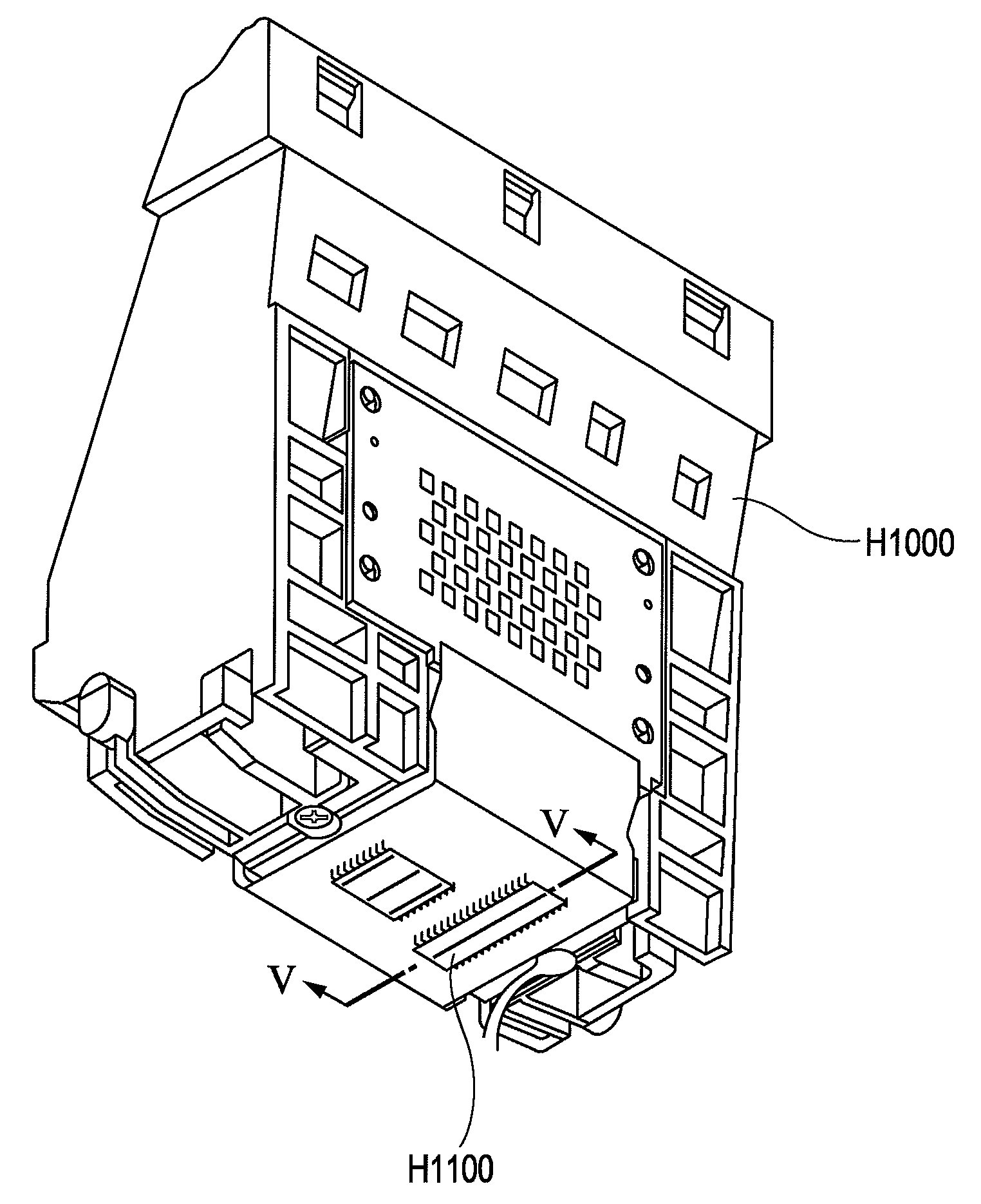
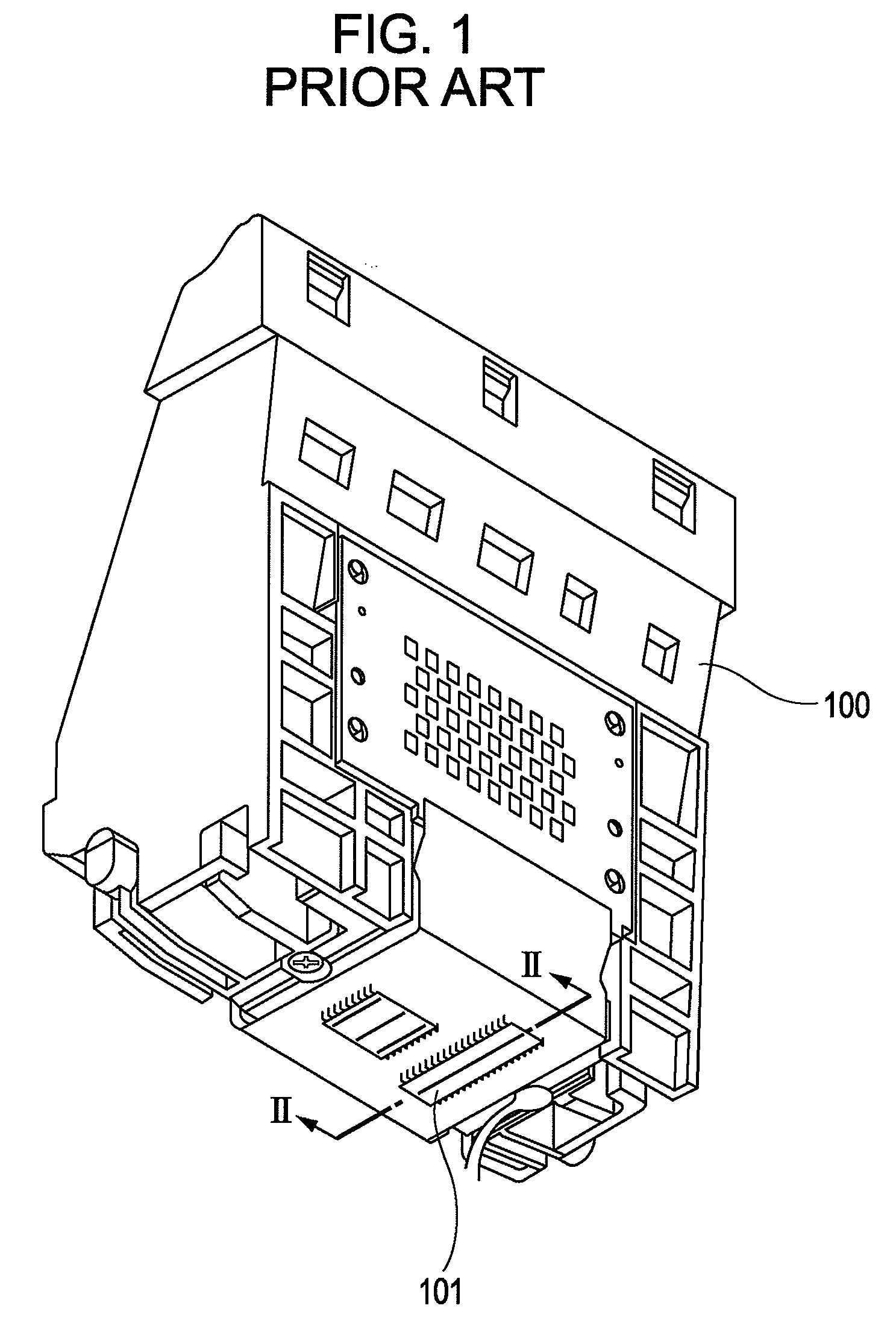
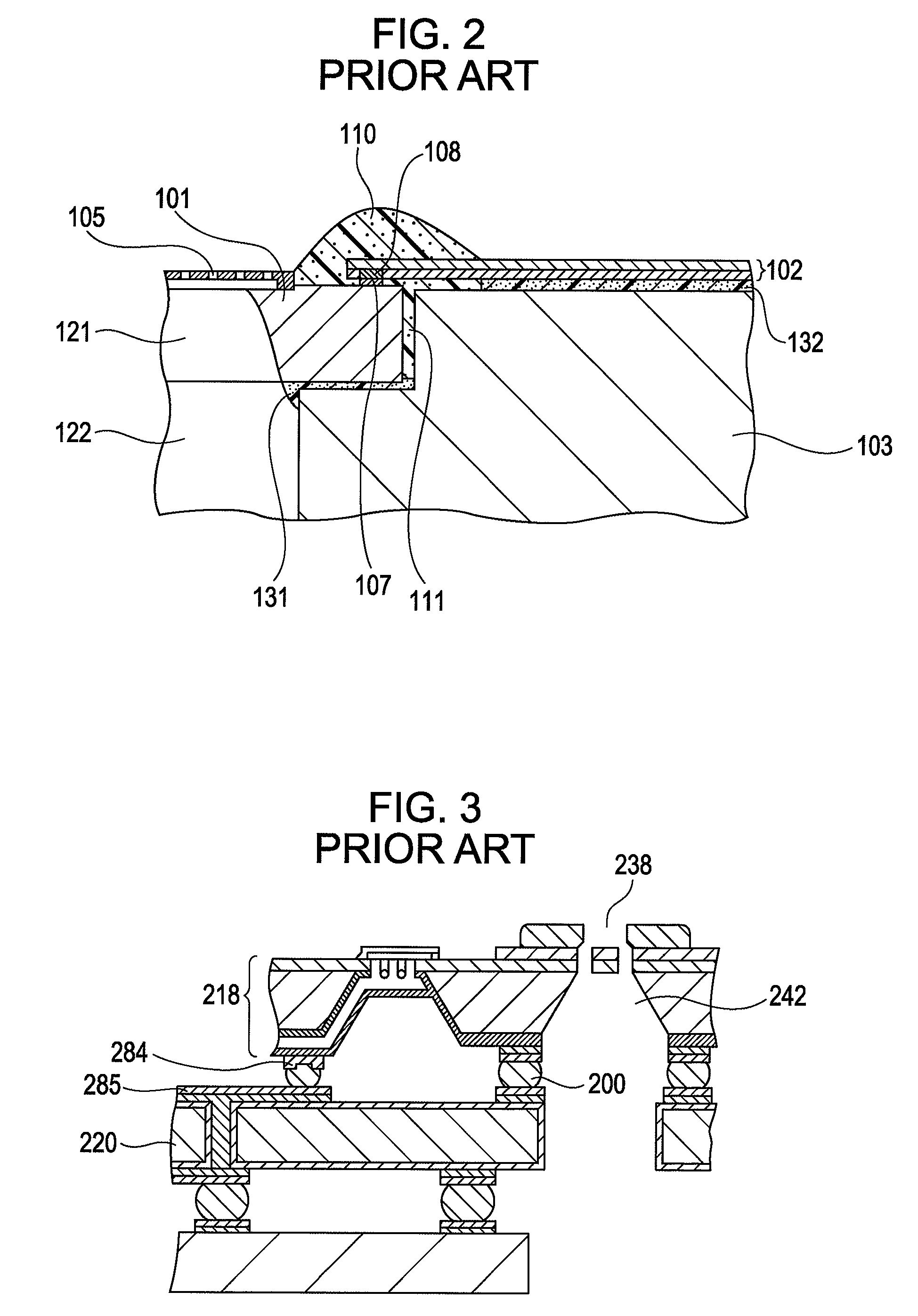
  • Sealant for ink jet head, ink jet head, and ink jet recording apparatus
  • Sealant for ink jet head, ink jet head, and ink jet recording apparatus
  • Sealant for ink jet head, ink jet head, and ink jet recording apparatus

Examples


examples

(EXAMPLES 9 TO 12) AND COMPARATIVE EXAMPLES (COMPARATIVE EXAMPLES 6 and 7) OF INK JET HEAD

[0092]In the second example of the ink jet head, the sealants of Examples 1 to 4 and Comparative Examples 1 and 2 (shown in Table 1) were used as a first sealant to form ink jet heads of Examples 9 to 12 and Comparative Examples 6 and 7. In the examples and the comparative examples, the thickness of the sealant from an electrode portion was constant, and curing conditions of the sealants included 100° C. for 1 hour and 180° C. for 1 hour.

[0093]In order to evaluate bonding reliability and electric connection reliability of the ink jet heads of Examples 5 to 12 and Comparative Examples 4 to 7, the above-described ink (i) was charged and stored at 60° C. for 2 months. Then, each of the ink jet heads was mounted on an ink jet recording apparatus to evaluate printing on 10,000 sheets of A4 paper.

[0094]The results of Examples 5 to 8 and Comparative Examples 4 and 5 are shown in Table 3, and the resul...


PUM

PropertyMeasurementUnit
Percent by massaaaaaaaaaa
Weightaaaaaaaaaa

Abstract

A sealant for an ink jet head includes at least an oxetane compound having a biphenyl skeleton, an alicyclic epoxy compound, and a cationic polymerization initiator.

Description

BACKGROUND OF THE INVENTION[0001]1. Field of the Invention[0002]The present invention relates to a sealant used for an ink jet head mounted on an ink jet recording apparatus for recording by ejecting ink to a recording sheet, an ink jet head, and an ink jet recording apparatus.[0003]2. Description of the Related Art[0004]An ink jet head used in an ink jet recording apparatus includes a discharge element substrate on which electrothermal transducers generating energy for discharge are provided. Electric pulses used for driving the electrothermal transducers are applied from the outside using a wiring substrate or the like. The wiring board and the discharge element substrate are electrically connected to each other by inner lead bonding (ILB). Such an electric connection portion is sealed with a sealant or an adhesive in order to prevent corrosion and short-circuiting of electrodes and wiring, which contribute to electric connection, due to mist of the ink filled at the time of disch...

Claims


Application Information

Patent Timeline
IPC IPC(8): B05D1/00B41J2/14C08L63/00B41J2/01B41J2/05B41J2/16C08G59/18
CPCB41J2/14072B41J2/1601B41J2/1623
Inventor HARADA, KOUJIIMAMURA, ISAO
Owner CANON KK
Learn More