

Submerged membrane bio-reactor
a bioreactor and submerged technology, applied in bioreactors/fermenters, biochemical water/sewage treatment, biomass after-treatment, etc., can solve the problems of reducing water yield (flux), affecting the use of mbrs, increasing the cost of operating and maintaining the submerged mbrs, etc., to reduce the resistance of a cake layer and reduce the flux
- Summary
- Abstract
- Description
- Claims
- Application Information
AI Technical Summary
Benefits of technology
Problems solved by technology
Method used
Image

Examples
example 1
Analysis of Two-Phase Flow in Cylindrical Tube
[0045]By increasing the amount of air supplied by a porous diffuser and a nozzle in steps of 0.5, 1.0, 1.5, and 2.0 L / min, amount Q, of the activated sludge liquid mixture escaped outside of the cylindrical tube was observed, and the measured amount Q, of the activated sludge liquid mixture did not show significant difference between the nozzle and the porous diffuser. Then, after measuring amounts Qg of air bubbles and Q, of liquid, ratio of the amount of air bubbles to liquid ε was calculated from Equation (2) below.
ɛ=QgQg+Ql(2)
[0046]Generally, the shape of two-phase flow changes according to ε value. As shown in FIG. 3, the two-phase flow changes to bubbly, slug, churn, and annular shapes as ε value is increased. In the cylindrical tube, air bubbles have a uniformed round shape in the bubbly-shape flow and slug (or bullet) shape which almost fills the cylindrical tube in the slug-shape flow. In the churn-shape flow, most of the liquid...
example 2
Effect of Preventing Membrane Contamination According to Method of Introducing Air into Cylindrical Tube
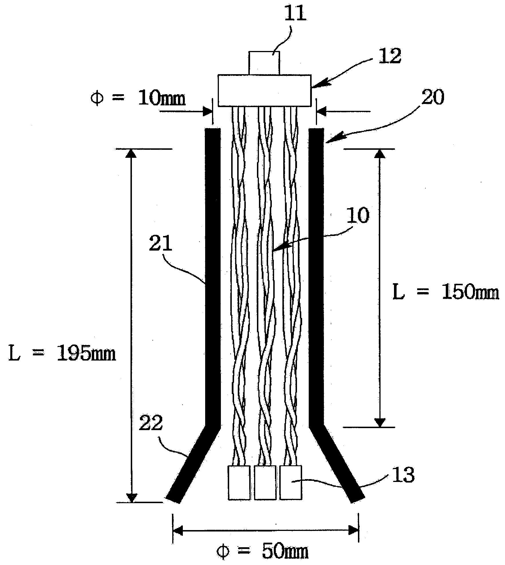
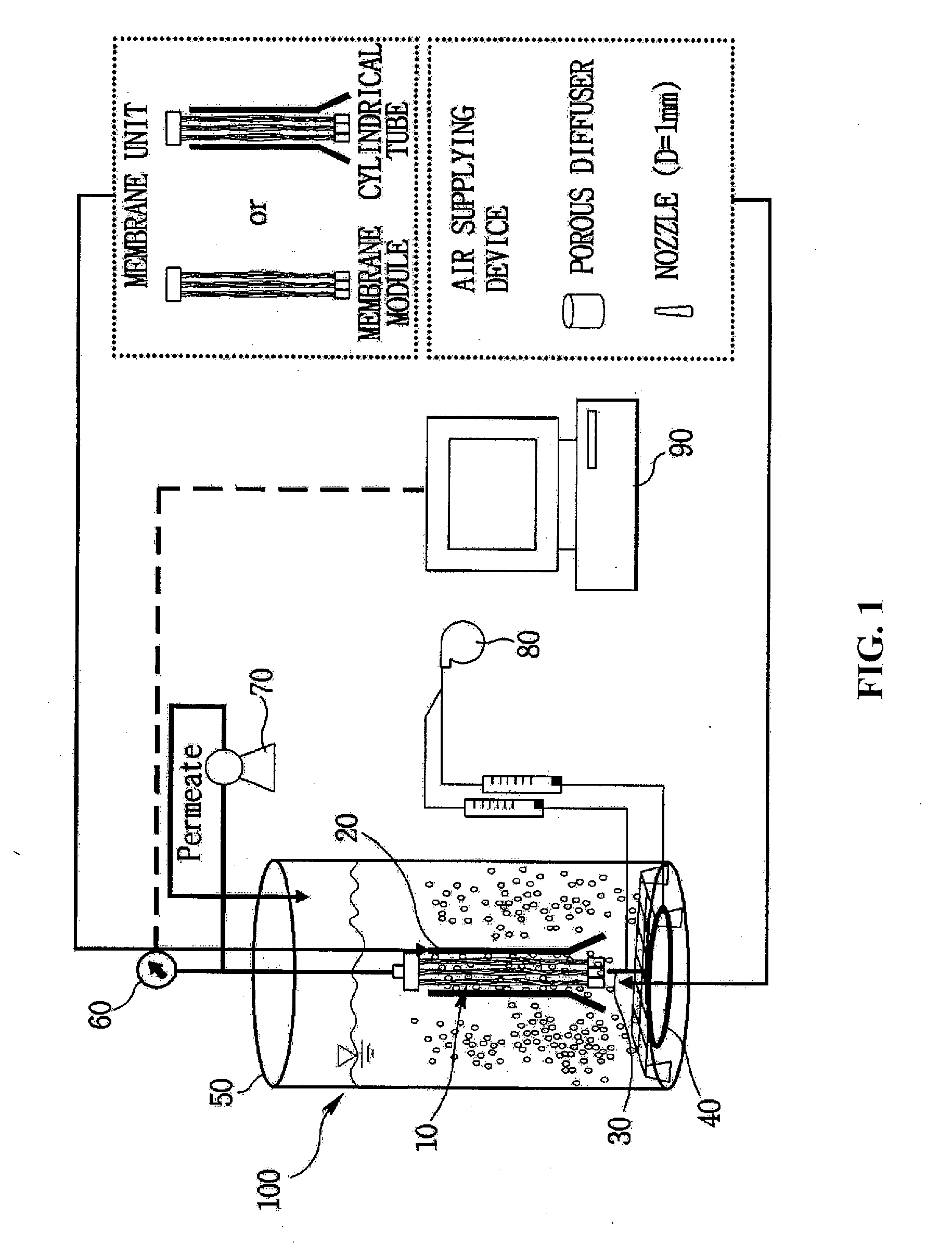
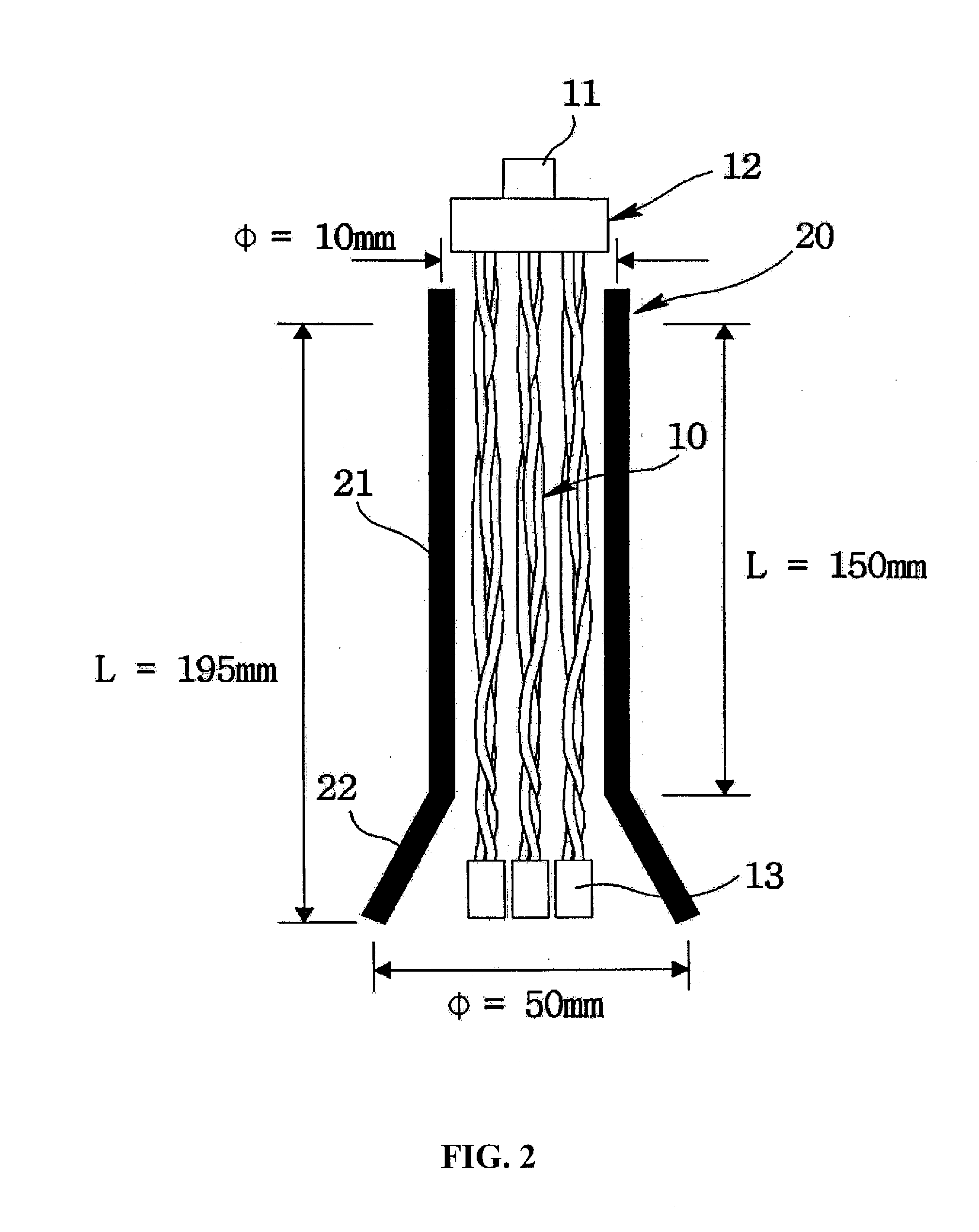
[0048]A membrane module (Run 1) having a total surface area of 0.0034 m2 (10 hollow-fiber membrane strands) covered by a cylindrical tube was submerged in an MBR having an MLSS density of 6,500 mg / L. Then, the MBR was operated for 600 minutes or until TMP reached 40 kPa by maintaining a flux of 24 lm−1h−1. A nozzle and a porous diffuser were provided below the cylindrical tube and air was supplied at varying rates. FIG. 4A shows change in TMP with respect to time. A control group of membrane modules without the cylindrical tube was arranged on the lower end of the MBR and was operated under the same condition to determine the effect of having the cylindrical tube.
[0049]For the control group, the amount of air supplied was increased from 0.3 L / min to 1.0 L / min and the time it took to reach TMP of 40 kPa did not show a significant difference. When the amount of air supplied was incr...
example 3
Contamination of Membrane Module Covered With Cylindrical Tube According to Flux
[0052]A membrane module (Run 2) having a total surface area of 0.0051 m2 (15 hollow-fiber membrane strands) covered by a cylindrical tube was submerged in an MBR having an MLSS density of 6,200 mg / L. Then, the MBR was operated for 600 minutes or until TMP reached 40 kPa by changing a flux of 24 lm−1h−1 to 35 lm−1h−1, and the change in TMP with respect to time was measured. In order to eliminate the effect from the intrinsic membrane resistance, Rt / Rm ratio was obtained from the measured TMP values. The amount of air supplied was maintained at 0.3 L / min.
[0053]As shown in FIG. 5, Rt / Rm ratio increased less at the flux of 24 lm−1h−1 than at the flux of 35 lm−1h−1. Further, as described in Example 2, it was determined that the nozzle is more effective than the porous diffuser in preventing membrane contamination. Here, when the flux was maintained at the higher rate, the activated sludge liquid mixture attra...
PUM
 Abstract
Description
Claims
Application Information