Diagnostic Testing Process and Apparatus Incorporating Controlled Sample Flow

a technology of lateral flow and test equipment, applied in the field of diagnostics, can solve the problems of increasing the risk of lateral flow failure, so as to prevent the build-up of pressure inside the casing

Inactive Publication Date: 2008-12-25
PROTEOME SYST LTD
View PDF1 Cites 31 Cited by
  • Summary
  • Abstract
  • Description
  • Claims
  • Application Information

AI Technical Summary

Benefits of technology

[0018]The absorbent body and reaction membrane may be located in a housing which defines at least one bleed aperture to prevent the build up of pressure inside the casing.

Problems solved by technology

However, multiple disease diagnosis using lateral flow technology is very difficult because of differences in lateral diffusion between samples and variation in flow rates between batches of the partitioning membranes.
This means that antigen or antibody signal strengths may vary both within tests and between batches of tests, resulting in inconsistent results.
This advantage in speed however, is often at the expense of sensitivity.
However, although the apparatus and method disclosed in PCT / AU02 / 01119 is an improvement over existing vertical flow-through devices it has been found that considerable variation in the results occurs.

Method used


Image

  • Diagnostic Testing Process and Apparatus Incorporating Controlled Sample Flow
  • Diagnostic Testing Process and Apparatus Incorporating Controlled Sample Flow
  • Diagnostic Testing Process and Apparatus Incorporating Controlled Sample Flow

Examples


Embodiment Construction

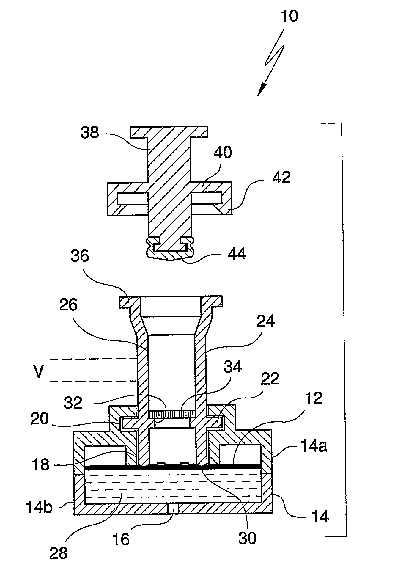
[0034]Capture analytes in the form of ligands such as antigens or antibodies are printed onto a protein capture membrane matrix, more particularly, a nitrocellulose membrane in an appropriately sized array using piezoelectric chemical printing technology or other printing technologies, such as syringe pump. A suitable chemical printing system involves the use of piezoelectric drop on demand inkjet printing technology for micro dispensing fluids, in DNA diagnostics or, a Combion Inc. synthesis process, called “CHEM-JET”. Such a device including an imaging means is also described in the Applicant's International Patent Application No. PCT / AU98 / 00265, the entire contents of which are incorporated herein by reference. In the described embodiment, antigen is printed onto a reactions membrane in 100 PL droplets, or multiples thereof with each aliquot being 1 mm apart. However, these volumes and distances can be increased / decreased accordingly depending on the chosen antigen titre and arra...


PUM

PropertyMeasurementUnit
volumeaaaaaaaaaa
pore sizeaaaaaaaaaa
pore sizeaaaaaaaaaa

Abstract

An apparatus (10) and method for use in a vertical flow-through assay process is characterised by applying pressure to a sample to force the sample through a reaction/capture membrane (12), to which one or more ligands are bound, at a controlled rate. Typically, the method includes a pre-incubation step in which the sample and a detection analyte typically an antibody bound to colloidal gold or a fluorescent tag bind together The pre-incubation step typically takes place in a chamber (26) spaced above the capture membrane (12). The base of the chamber is defined by a porous hydrophobic frit (34) typically formed from polyethylene. It is preferred that the chamber (26) is defined by the upper part of a cylinder (24) extending from a seal (30) compressing the reaction membrane (12) against an absorbent pad (28). The seal (30) has the effect of compressing tie reaction membrane and preventing wicking of the sample in the lateral direction outside of the circular seal. A piston (28) compresses air located in the chamber above atmospheric pressure to farce the sample to pass through the hydrophobic frit (34). Alternatively, a hydraulic actuator (60) may directly act on the sample to force the sample through the frit and reaction membrane at a predetermined rate.

Description

CROSS-REFERENCE TO RELATED APPLICATIONS[0001]The present application claims priority from Provisional patent application Ser. No. 2004903009 filed on 4 Jun. 2004, the content of which is incorporated herein by reference,FIELD OF THE INVENTION[0002]This invention relates to a diagnostic testing process and apparatus. In particular, the invention relates to an apparatus for use in carrying out an assay process incorporating controlled flow of the sample being assayed and to a method of carrying out all assay process incorporating controlled flow.BACKGROUND OF THE INVENTION[0003]Lateral flow and flow-through technology have been used for diagnostic assays for almost twenty years. Lateral flow technology is currently dominant because lateral flow devices are easy to produce and the assay can be performed in a simple two step process that can be adapted for whole blood separation. This results in a simple device that can be used in the field as a rapid point-of care diagnostic (see Cole ...

Claims


Application Information

Patent Timeline
Patent Type & Authority Applications(United States)
IPC IPC(8): G01N33/553B01J19/00G01N33/543B01L3/00G01N33/52
CPCB01L3/50255B01L2300/0825B01L2300/0829B01L2300/16B01L2400/0406B01L2400/0478B01L2400/0633G01N33/54386
Inventor DURACK, MATTHEW C. A.BULS, ROWAN
Owner PROTEOME SYST LTD
Why Eureka
Try Eureka