
Radial Expansible Retractor For Minimally Invasive Surgery

a retractor and radial axis technology, applied in the field of radial axis retractor for minimally invasive surgery, can solve the problems of brain tissue infarction, long procedures, trauma to brain tissue, etc., and achieve the effects of less brain damage, improved performance, and reduced post-operation death ra

Active Publication Date: 2008-12-25
MICRODEL IDEA CENT LTD
View PDF17 Cites 73 Cited by
  • Summary
  • Abstract
  • Description
  • Claims
  • Application Information

AI Technical Summary

Benefits of technology

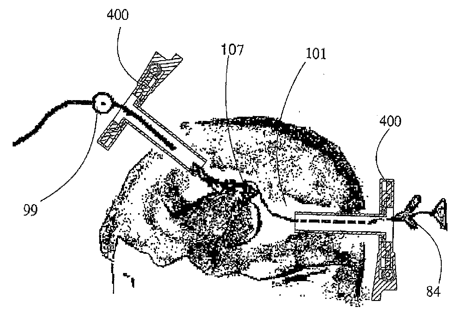
[0026]It is an objective of the present invention to provide the means to open a channel in the brain or any other organ of a patient, through which the area designated for treatment can be seen, and through which surgical tools can be inserted for treatment, such as extracting a tissue sample for biopsy, or performing excision or suction of tissue for the purpose of removing a cancerous tumor etc. According to the present invention, a retractor of improved performance with regard to the performance of standard retractors is used and enables performance of medical procedures in previously unattainable depths in the brain, and in a patient-friendly manner in comparison with the insertion of standard retractors into the brain, which results in less brain damage to recovering patients, as well as a lower post-operation death rate.
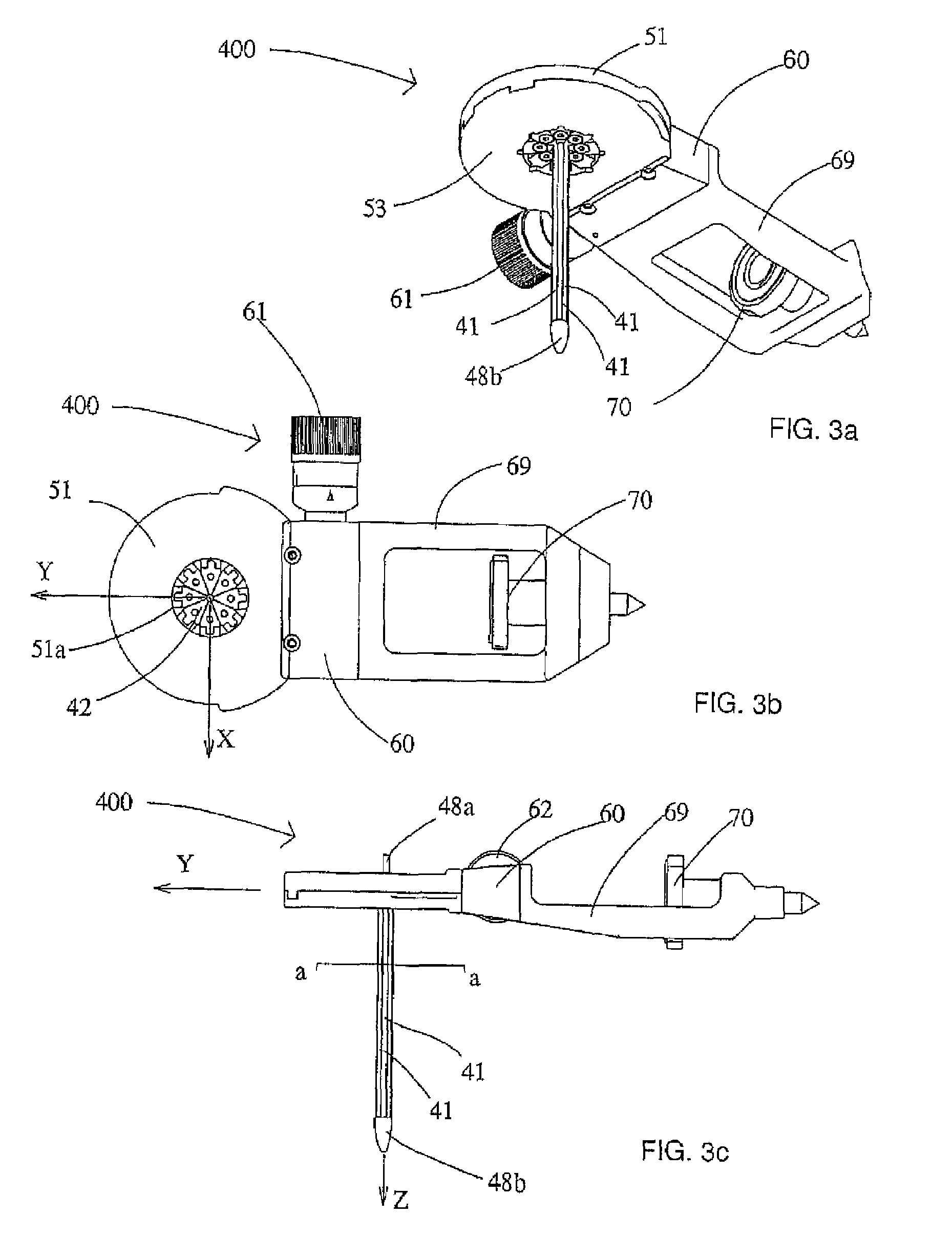
[0027]The retractor according to the present invention is connected stably to a device which can be attached to die operation table on which the patient is prone. After drilling a hole of a suitable diameter in the skull, in the case of brain surgery, the retractor is inserted into the patient's brain under the surveillance of an imaging system such as MRI or any other of sufficient resolution to prevent damage to brain neural fibers. After insertion into the required depth and location, the retractor is opened gently, at a suitable opening rate and force. The retractor is composed of several ribs of a suitable length creating a lateral cross section shaped compatibly with the desired cross section of the channel. Usually, when the retractor is closed, the ribs form the shape of a closed cylinder with walls of a sufficient width to ensure the necessary structural integrity, with each rib serving as a segment of the cylinder's section. For example, when the cylinder's section is circular, and the number of ribs is eight, each rib will have a cross section of a circular arc with an opening angle of 45 degrees. This structure of the retractor prevents the formation of non-uniform pressures on the different brain areas coming into contact with the retractor.

Problems solved by technology

a. infarction of brain tissue due to the localized pressure to which the retracted portions of the brain are subjected;
b. bleeding upon insertion of the retractors;
c. if several retractors need to be inserted, the pressure on the brain tissue is uneven, the lesion may not be properly exposed, possibly leading to a need to perform supplementary surgery in order to remove any remaining tumor tissue; or
d. insertion of the retractors and separation of the brain lobes are performed manually; these motions are thus inherently uneven, and are liable to cause trauma to the brain tissue.
Procedures are very lengthy and a number of surgical procedures are not carried at all out due to risk factors, or cannot be carried out successfully using current techniques.
Increased dislocation and pressure on the brainstem could cause cessation of breathing and death of the patient.
This method has several main disadvantages, including the opening applying uneven pressure on brain tissue, the retractor's force is exerted only in the single direction or single dimensional of the linear opening.
Furthermore, the retractor, which is hand-held by the human operator, is insufficiently stable, and any slight tremor of the operator's hands could damage brain tissue.
In spite of the significant improvement that this means provides over the previous generation, it still does not provide sufficient uniformity of the pressure applied on the brain tissue.
This method requires anesthetizing the patient more than once, thus increasing the risk to his life.

Method used


Image

  • Radial Expansible Retractor For Minimally Invasive Surgery
  • Radial Expansible Retractor For Minimally Invasive Surgery
  • Radial Expansible Retractor For Minimally Invasive Surgery

Examples


Embodiment Construction

[0099]The present invention is an Improved Radial Expansible Retractor (IRER) for Minimally Invasive Surgery (MIS).

[0100]The principles and operation of an IRER according to the present invention may be better understood with reference to the drawings and the accompanying description.

[0101]Before explaining at least one embodiment of the invention in detail, it is to be understood that the invention is not limited in its application to the details of construction and the arrangement of the components set forth in the following description or illustrated in the drawings.

[0102]Unless otherwise defined, all technical and scientific terms used herein have the same meaning as commonly understood by one of ordinary skill in the art to which this invention belongs. The materials, dimensions, methods, and examples provided herein are illustrative only and are not intended to be linking.

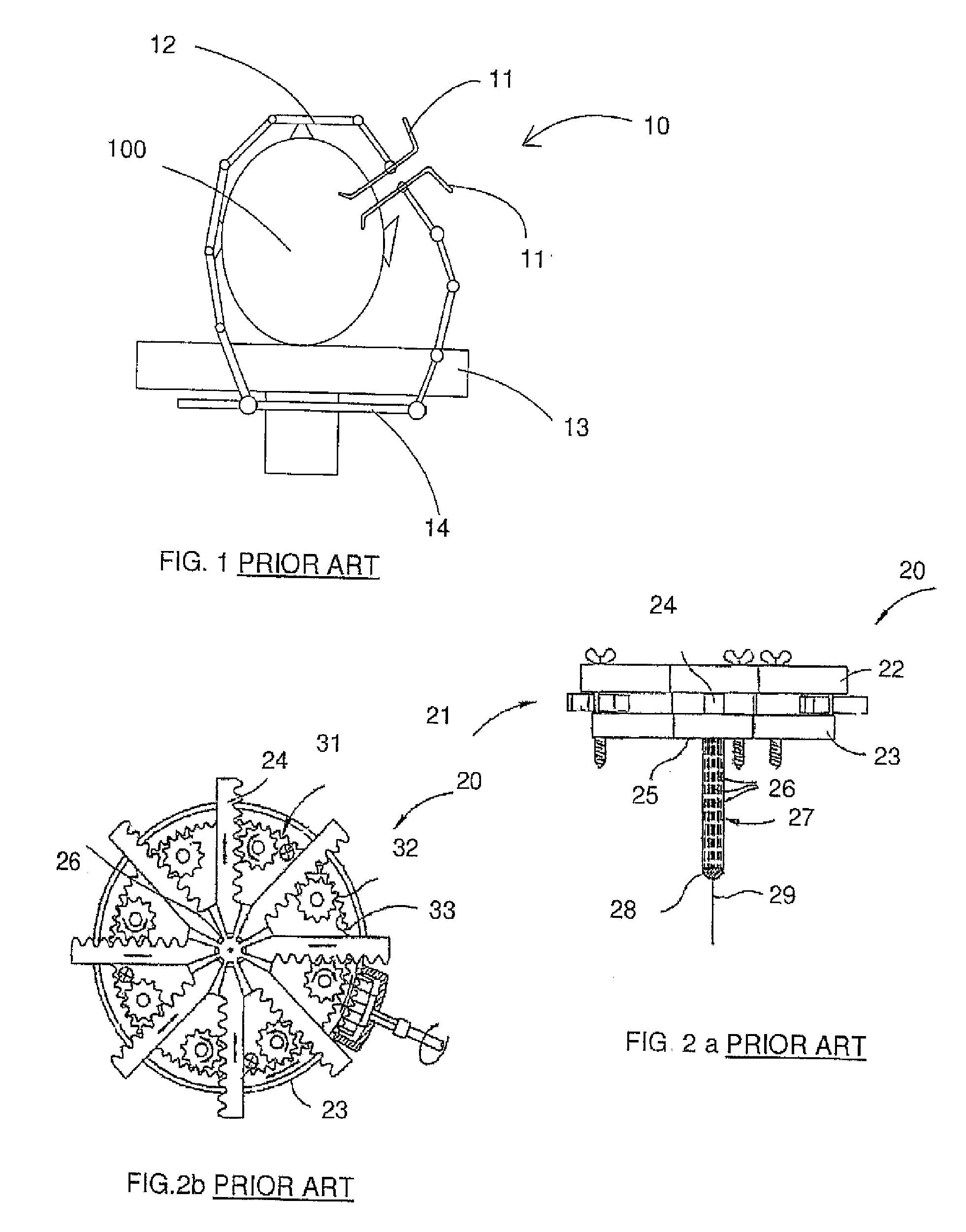
[0103]The following list is a legend of the numbering of the application illustrations:[0104]11 spatula[01...


PUM


Abstract

An improved radial expansible retractor and a method of minimally invasive surgery, by opening a channel in the brain or other soft tissue of a patient, by inserting the radial expansible retractor into the body of the patient, and by widening the channel at a continuous and gentle rate. The use of the improved radial expansible retractor renders surgical procedures, including neurosurgical procedures, shorter, less traumatic, and more reliable, reducing risk and the need for subsequent surgery and reducing recovery time. Procedures are carried out with real time monitoring of the retracted brain perfusion pressure. A plurality of improved radial expansible retractors may be used in a single operation. The improved radial expansible retractor allows access to areas of the brain previously almost impossible to access.

Description

FIELD AND BACKGROUND OF THE INVENTION[0001]The present invention relates to apparatus and techniques for performing minimally invasive surgery and, in particular to a retractor device for minimally invasive surgery.[0002]Minimally invasive surgical techniques are becoming increasingly widespread in many different surgical fields. An area in which such techniques would appear to be particularly relevant is neurosurgical removal of Space-Occupying lesions (SOL), Intra Cerebral Hemorrhages (ICH), Intra Ventricular Hemorrhages (IVH), Intra Axial Brain Tumors (IABT), Intra Ventricular Brain Tumors (IVBT), and Other Brain lesions (OBL) and Brain Pathological Conditions (BPC).[0003]In accordance with current methods, following initial imaging for locating a brain lesion, die skull is trepanned so as to remove a bone flap exposing an opening in the skull surface, an opening of from 1 cm×1 cm tip to 5 cm×5 cm, after which retractors are inserted into the brain tissue or lobes, and used to mo...

Claims


Application Information

Patent Timeline
Patent Type & Authority Applications(United States)
IPC IPC(8): A61B1/32
CPCA61B17/0218A61B17/0293A61B17/3439A61B17/3476A61B2017/00907A61B90/30A61B2090/065
Inventor MICHAELI, DAVIDMICHAELI, MICHAEL
Owner MICRODEL IDEA CENT LTD
Learn More