
Near Halfwave Retarder For Contrast Compensation

a liquid crystal display and contrast compensation technology, applied in the field of near halfwave retarder, can solve the problems of difficult to form true zero-order retarders, difficult to polish birefringent crystal plates to physical thicknesses less than 100 microns, and significantly lower on-state/off-state contrast ratios, etc., to achieve the effect of improving on-state/off-state contrast ratio, improving contrast ratio, and improving contrast ratio

Inactive Publication Date: 2009-01-01
JDS UNIPHASE CORP
View PDF5 Cites 25 Cited by
  • Summary
  • Abstract
  • Description
  • Claims
  • Application Information

AI Technical Summary

Benefits of technology

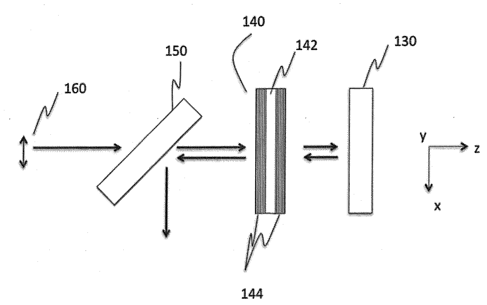
[0020]The instant invention relates to contrast compensation in liquid crystal display (LCD) projector systems, where the LCD exhibits small magnitude residual in-plane retardance in the off-state. The contrast compensation is provided with a near zero-order half-wave retarder. Advantageously, the near half-wave retarder delivers optimal dark-state crossed polarization output without appreciably degrading the on-state, in WGP-based LCoS projection systems. Furthermore, the near half-wave retarder is readily fabricated using a single-layer birefringent crystal with a manageable thickness tolerance. In addition, the near half-wave retarder exhibits an angular sensitivity comparable to prior art small magnitude trim retarders.
[0021]In accordance with one aspect of the instant invention there is provided a liquid crystal display projection system comprising: a reflective liquid crystal display panel having residual off-state birefringence at a predetermined wavelength; and a trim retarder for compensating for the residual off-state birefringence of the reflective liquid crystal display panel and for increasing an on-state / off-state contrast ratio of the liquid crystal display projection system, wherein the trim retarder includes a single-layer retarder element having an in-plane retardance for compensating for an in-plane component of the residual off-state birefringence, the in-plane retardance shifted from a half-wave at the predetermined wavelength by a predetermined amount, the predetermined amount less than about 0.15 wave at the predetermined wavelength.
[0022]In accordance with one aspect of the instant invention there is provided a method of improving contrast ratio in a liquid crystal display projection system, the method comprising: providing a trim retarder for compensating for residual off-state birefringence of a reflective liquid crystal display panel in the liquid crystal display projection system, the trim retarder including a single-layer retarder element having an in-plane retardance for compensating for an in-plane component of the residual off-state birefringence, the in-plane retardance shifted from a half-wave at the predetermined wavelength by a predetermined amount, the predetermined amount less than about 0.15 wave at the predetermined wavelength.
[0023]In accordance with another aspect of the instant invention there is provided a method of improving contrast ratio in a liquid crystal display projection system, the method comprising: determining a residual off-state retardance of a reflective liquid crystal display panel in the liquid crystal display projection system; determining a first in-plane retardance for compensating for the residual off-state retardance and for increasing an on-state / off-state contrast ratio of the liquid crystal display projection system; and positioning a trim retarder in the liquid crystal display projection system, the trim retarder including a single-layer retarder element having a second in-plane retardance, the second in-plane retardance substantially equal to one of a half-wave plus the first in-plane retardance and a half-wave minus the first in-plane retardance, the first and second in-plane retardances determined at a same wavelength in a visible region of the electromagnetic spectrum.

Problems solved by technology

As is well known in the art, this residual off-state birefringence typically leads to off-state leakage, which manifests as a bright dark-state that is very obvious when displaying dark video content, and which significantly lowers the on-state / off-state contrast ratio.
However, for materials having a relatively high birefringence, such as some inorganic crystals and / or LCP materials, forming a true zero-order retarder is challenging.
I practice, it is very difficult to polish birefringent crystal plates to physical thicknesses less than about 100 microns (e.g., they are too thin for easy fabrication and handling).
Unfortunately, both of these embodiments require an increased number of components and thus, are associated with increased manufacturing costs.
In addition, there is also increased cost related to the required relative alignment.
Although calculations have shown that clocking characteristics of multiple order retarders may be similar to their zero-order counterparts, they are not generally ideal for trim retarder applications due to their high dispersion.
Even assuming that the quartz retarders are utilized in the green-band (e.g., instead of the entire visible band), the simulated results clearly indicate that the net retardance of the multiple-order quarter-wave plate does not allow for optimal contrast compensation beyond the design wavelength.
Unfortunately, since compensator requirements for WGP-based polarization beam-splitting devices can differ significantly from those based on a MacNeille PBS, this approach has not provided a successful solution to contrast compensation in WGP-based LCoS microdisplay projection systems.
Notably, this approach is also not expected to provide a successful solution to contrast compensation in WGP-based LCoS microdisplay systems.
For example, as discussed above, the use of a quarter-wave plate is associated with poor performance in WGP-based LCoS microdisplay systems, whereas the use of a half-wave plate is expected to cause the panel on-state brightness to decrease such that the resulting sequential contrast (full on / full off) is negatively affected and system throughput degraded.
In addition, aligning the second half-wave plate to approximately half the angle offset of a second quarter-wave plate from the S- or P-axis does not work.

Method used


Image

  • Near Halfwave Retarder For Contrast Compensation
  • Near Halfwave Retarder For Contrast Compensation
  • Near Halfwave Retarder For Contrast Compensation

Examples


Embodiment Construction

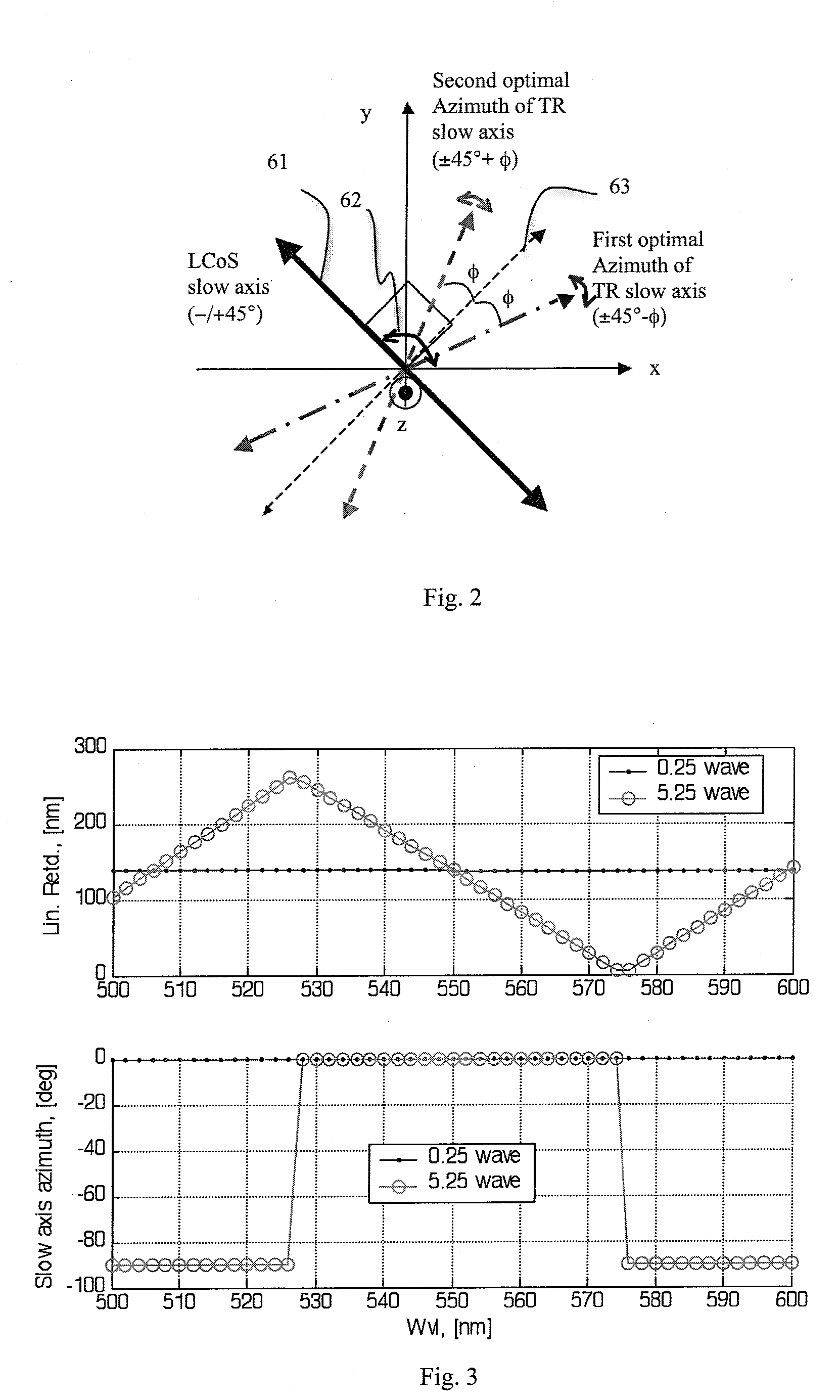
[0040]In order to provide an improved trim retarder for a WGP-based LCoS microdisplay system it is necessary to look at some of the preferred characteristics of trim retarders. Ideally, a trim retarder should be able to (a) deliver extremely low crossed-polarization leakage in the light off-state; (b) deliver nearly unchanged crossed-polarization output in the light on-state of the compensated panel versus uncompensated panel; (c) exhibit good mechanical clocking sensitivity for the initial alignment (i.e., when clocking is required) and for long-term alignment drift; (d) provide a high contrast ratio of on-state intensity versus off-state intensity over a given red, green, blue band or the entire visible wavelength band; and (e) exhibit good retardation magnitude and orientation uniformity.

[0041]Moreover, in addition to providing in-plane retardance, it may be advantageous for the trim retarder to provide out-of-plane retardance. While in-plane retardance is typically provided with...


PUM


Abstract

Contrast compensation for a liquid crystal display projection system is provided with a trim retarder that includes a single-layer retarder element that has an in-plane retardance that is shifted from a zero-order half-wave at a predetermined wavelength by a predetermined amount. This near half-wave plate provides similar contrast compensation and azimuthal angle sensitivity to conventional relatively low-magnitude trim retarders, yet is readily fabricated with inorganic birefringent crystals with a manageable thickness tolerance.

Description

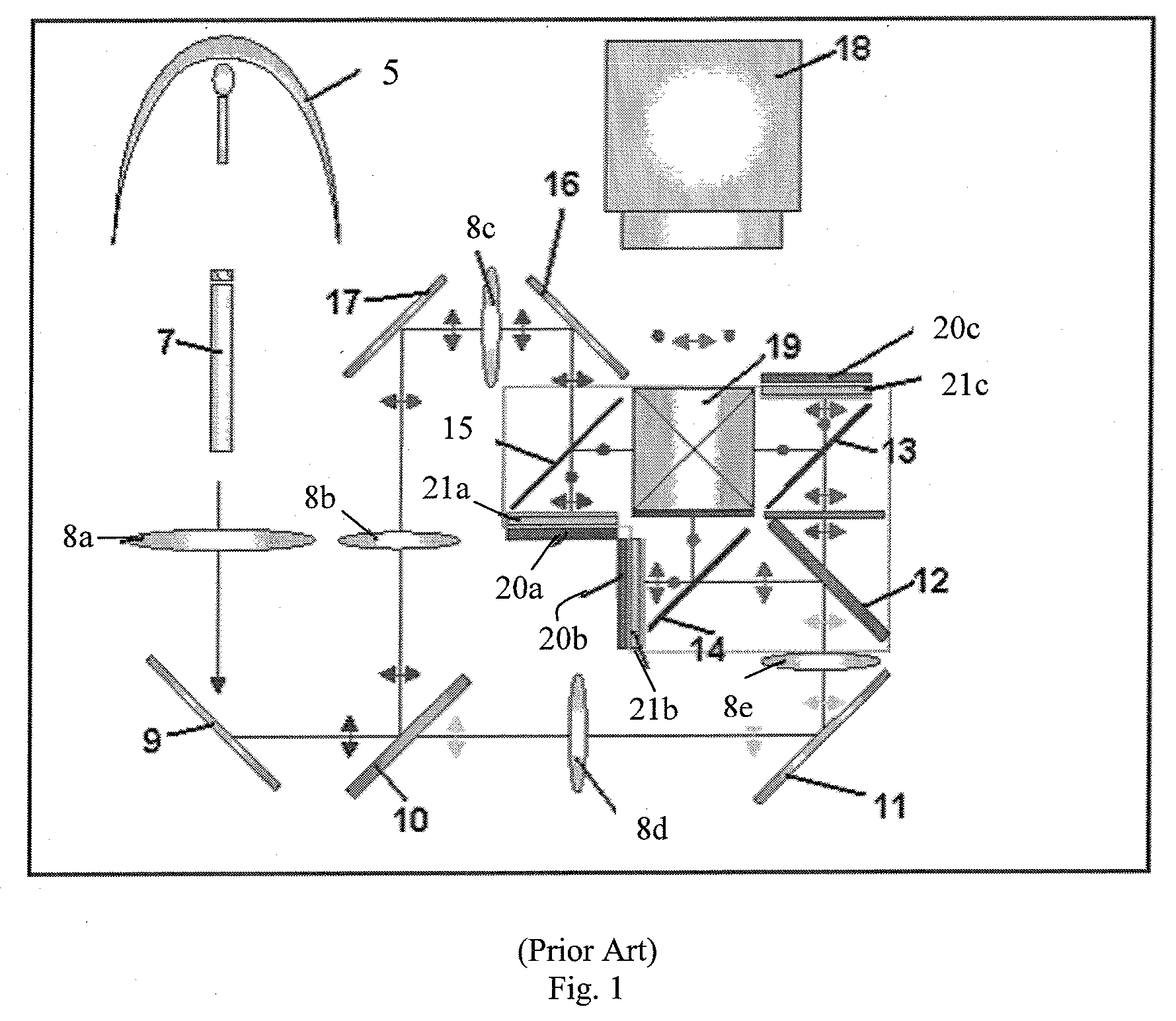
CROSS-REFERENCE TO RELATED APPLICATIONS[0001]This application claims priority from U.S. Provisional Application No. 60 / 947,156, filed Jun. 29, 2007, which is hereby incorporated by reference.MICROFICHE APPENDIX[0002]Not Applicable.TECHNICAL FIELD[0003]The present application relates generally to contrast compensation for liquid crystal displays, and in particular, to contrast compensation of liquid crystal displays used in high light flux projections systems.BACKGROUND OF THE INVENTION[0004]Liquid-crystal displays (LCDs) are widely used in projection displays for large screen televisions and monitors. One particularly successful LCD-based projection system is a WGP-based LCoS microdisplay system, which uses both wire grid polarizers (WGPs) and liquid crystal on silicon (LCOS) panels. This projection system, which has been proven to exhibit both high resolution and high image contrast when compared to other microdisplay technologies such as transmissive liquid crystal (xLCD), digital...

Claims


Application Information

Patent Timeline
IPC IPC(8): G02F1/1335
CPCG02F1/13363G02F1/136277G02F2413/07G02F2203/02G02F2413/03G02F2202/40H04N5/74
Inventor TAN, KIM LEONG
Owner JDS UNIPHASE CORP
Learn More