
Low-repetition-rate ring-cavity passively mode-locked fiber laser

a fiber laser and low repetition rate technology, applied in the field of fiber lasers, can solve the problems of spurious reflection in every laser cavity, increased fiber cavity length, and detrimental nonlinearities of optical fiber, and achieve the effect of low repetition ra

Inactive Publication Date: 2009-01-01
CORNING INC
View PDF6 Cites 39 Cited by
  • Summary
  • Abstract
  • Description
  • Claims
  • Application Information

AI Technical Summary

Benefits of technology

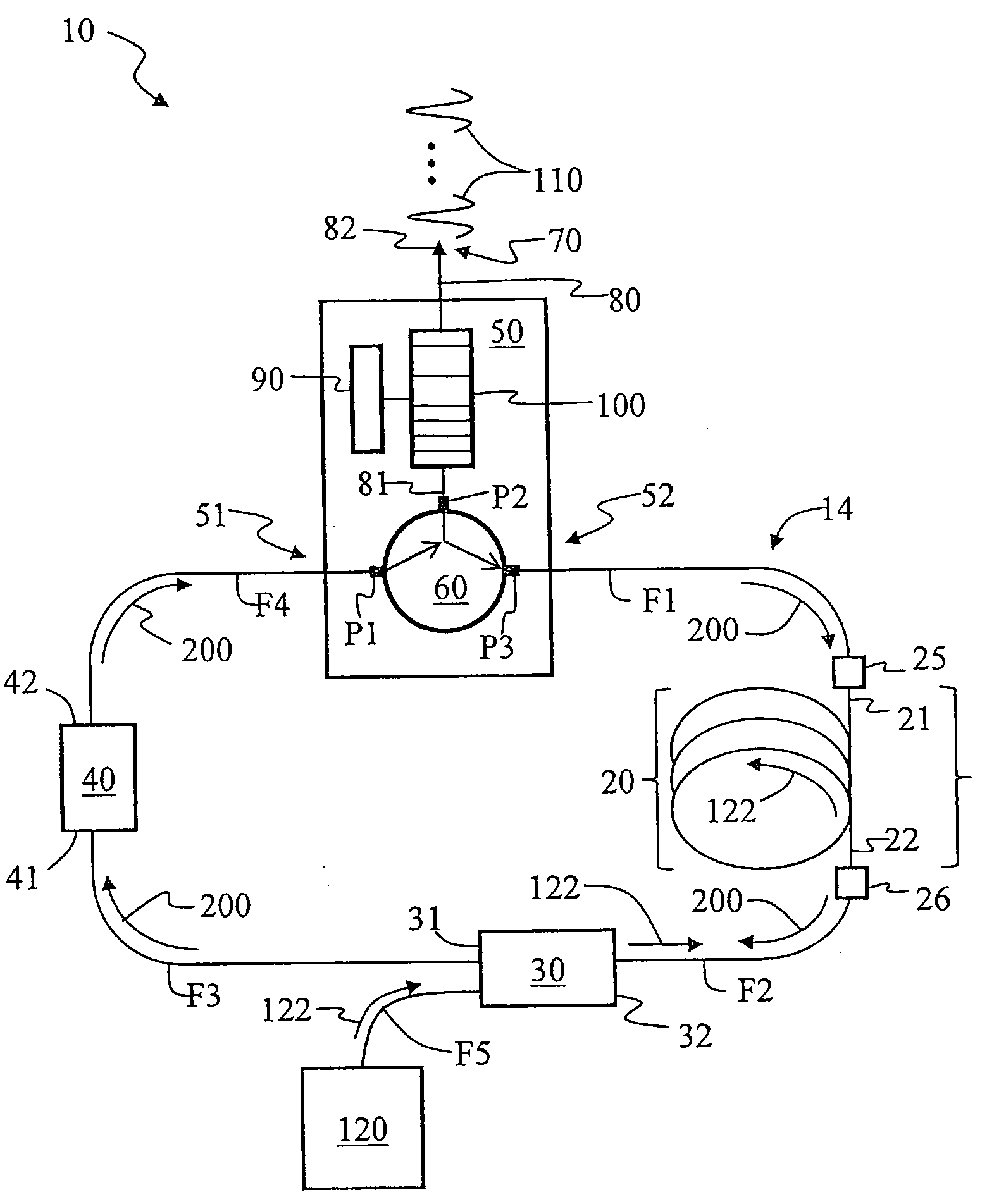
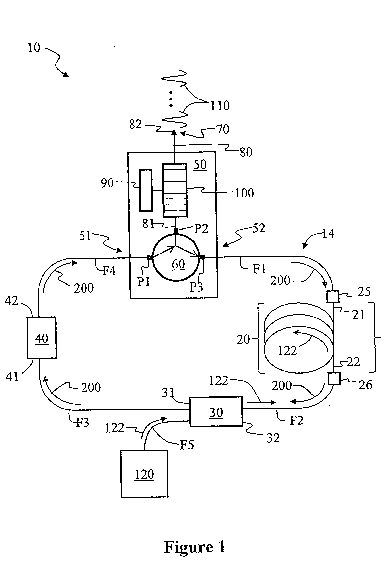
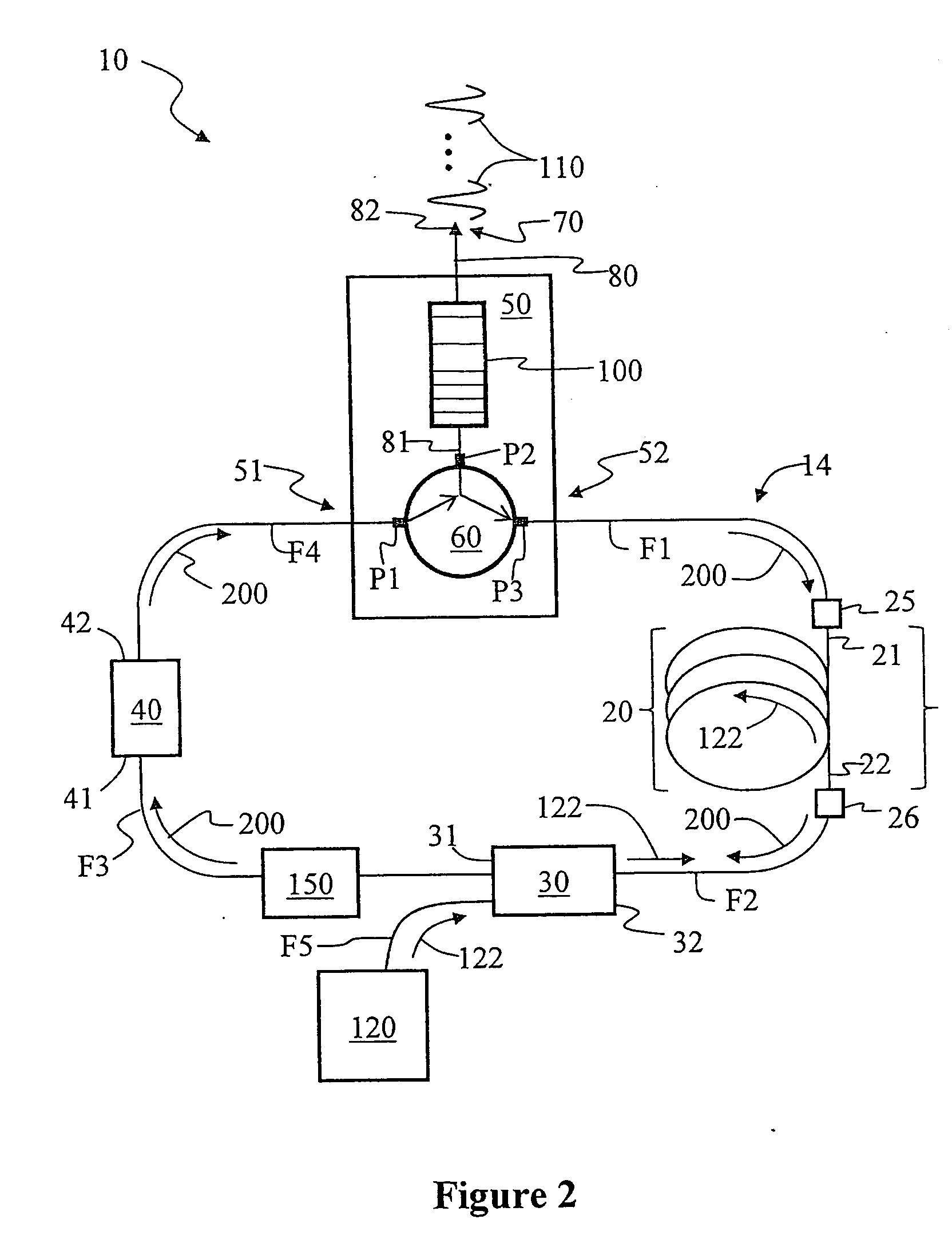
The invention is a fiber laser apparatus that can produce optical pulses with a low repetition rate. It includes a ring cavity that supports multiple modes and a dispersion compensator with a CFBG reflector. The apparatus also includes a doped optical fiber section that absorbs pump light and emits laser light at a different wavelength. A saturable absorber is used to effect passive mode-locking of the multiple modes to produce optical pulses at the laser wavelength. The apparatus can produce optical pulses with a low repetition rate of 2 MHz to 20 MHz. A pump light source is used to pump the gain medium.

Problems solved by technology

On the other hand, increasing the fiber cavity length gives rise to detrimental nonlinearities in the optical fiber.
Also, every laser cavity contains spurious reflections.

Method used


Image

  • Low-repetition-rate ring-cavity passively mode-locked fiber laser
  • Low-repetition-rate ring-cavity passively mode-locked fiber laser
  • Low-repetition-rate ring-cavity passively mode-locked fiber laser

Examples


specific example embodiment

[0047]FIG. 3 is a specific example embodiment of the ring-cavity passively mode-locked fiber laser 10 of the present invention as constructed by the inventor based on the above-described generalized embodiments. Saturable absorber 40 was formed using a three-port circulator 60 and a semiconductor-based saturable-absorber mirror (SAM) 46 having a recovery time of about 10 ps. SAM 46 was optically coupled to input / output port P2 via an optical fiber section F6. A highly Yb-doped optical fiber having a length of 1 m was used for doped optical fiber section 20.

[0048]CFBG 100 was an off-the-shelf grating having a center wavelength of 1051 nm, a reflectivity of 96%, and a bandwidth of 15.5 nm. While the particular CFBG 100 used did not have optimized properties, it provided good performance and confirmed the basic operating principles of the invention. The various optical fiber sections F1 through F4 and optical fiber section 20 used to form ring cavity 14 had normal dispersion around the...


PUM


Abstract

A ring-cavity, passively mode locked fiber laser capable of producing short-pulse-width optical pulses at a relatively low repetition rate. The fiber laser uses a one-way ring-cavity geometry with a chirped fiber Bragg grating (CFBG) at its reflecting member. The CFBG is part of a dispersion compensator that includes an optical circulator that defines a one-way optical path through the ring cavity. A doped optical fiber section is arranged in the optical path and serves as the gain medium. A pump light source provides the pump light to excite the dopants and cause the gain medium to lase. A saturable absorber is operable to effectuate passive mode-locking of the multiple modes supported by the ring cavity. The ring cavity geometry allows to achieve mode locking with single pulse operation in a longer cavity length than conventional linear cavities. Furthermore, the longer cavity length reduces the constraints on the chirp rate of the CFBG. This, in turn, allows the CFBG to have a relatively high reflectivity, which provides the necessary dispersion compensation and cavity loss for generating short optical pulses at a low repetition rate.

Description

BACKGROUND OF THE INVENTION[0001]1. Field of the Invention[0002]The present invention relates to fiber lasers, and in particular to passively mode-locked fiber lasers.[0003]2. Technical Background[0004]Short optical pulses (e.g., pulses having a temporal pulse width on the order of picoseconds or shorter) have many important applications in a variety of fields, including laser-based micromachining, thin film formation, laser cleaning, medicine, and biology. Optical pulse fiber laser systems are increasingly displacing traditional solid-state laser systems in applications requiring short optical pulses. A high-energy-pulse fiber laser system typically includes an seed pulse fiber laser and a multiple stage fiber amplifier. Self-started passively mode-locked fiber lasers are ideal pulse seed sources for such laser systems because they are compact, low cost, and have superior mechanical and thermal stability. A mode-locked fiber laser includes a section of doped optical fiber as the ga...

Claims


Application Information

Patent Timeline
Patent Type & Authority Applications(United States)
IPC IPC(8): H01S3/30
CPCH01S3/06725H01S3/0675H01S3/06791H01S3/08H01S3/1618H01S3/094042H01S3/09415H01S3/1055H01S3/1118H01S3/08009
Inventor LI, SHENPING
Owner CORNING INC
Learn More