
Fluidizing gravity conveyor with high temperature multi-layered fluid distributor member

Active Publication Date: 2009-01-01
FLSMIDTH AS
View PDF7 Cites 11 Cited by
  • Summary
  • Abstract
  • Description
  • Claims
  • Application Information

AI Technical Summary

Benefits of technology

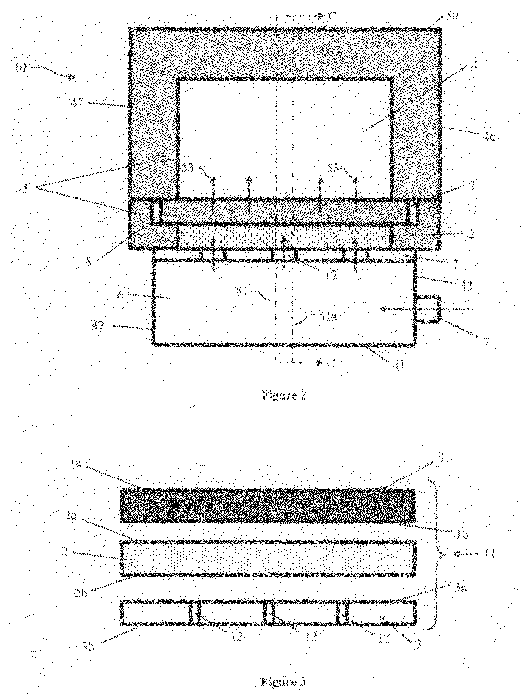
[0007]The distributor member has a smooth upper heat resistant layer that supports the material being conveyed, and preferably has three layers. The upper layer that serves as the upper surface supporting the material is a substantially smooth, gas permeable, substantially incompressible, porous medium capable of withstanding the high temperature in the material chamber, and which further provides many small holes through which fluidizing gas will pass for the hot material. The upper layer protects the under layers of the distributor from the flowing, hot material, and is of a material that will not react with or erode away when exposed to the high temperature material being conveyed in a given application. For example, in cement application the material will not be adversely affected by high temperature lime and alkalis, among other materials. The middle layer is a porous, gas permeable high temperature insulation that reduces the temperature gradient across the upper layer and protects the lower layer from the high temperature present in the upper material chamber. The lower layer is a perforated (or porous) support material that supports the upper layers and provides the pressure drop used to evenly distribute the conveying air to the upper layers. Each layer performs specific functions that allow the multi-layered fluid distributor, that typically is made from common materials, to operate at a higher temperature differential then a distributor made from a single component. In one embodiment, a three layer distributor is used in a fluidizing gravity conveyor to convey hot powdered material at temperatures greater than 1200° F. up to about 2900° F., and most typically up to about 1800° F.

Problems solved by technology

This is generally satisfactory for most applications; however typical aeration fabrics used for fluidizing gravity conveyors have a maximum temperature of 500° F. and are not suitable to evenly distribute a cold fluid from a plenum chamber to an adjacent high temperature material chamber.
If high temperature materials are to be conveyed with a fabric gas permeable member the fabric may ignite and destroy the conveyor.
Many commercially available porous materials otherwise suitable for use in ambient conditions can not withstand the high temperature or the thermal shock (defined as large thermal stresses caused by the large temperature differential between the material chamber and the plenum chamber as seen by the opposing sides of the distributor member).
The conveyors taught by such patents may not be optimum for certain types of material since the protruding tubes, bubble caps or nozzles may cause such material to clump and form obstructions to the material flow.

Method used


Image

  • Fluidizing gravity conveyor with high temperature multi-layered fluid distributor member
  • Fluidizing gravity conveyor with high temperature multi-layered fluid distributor member
  • Fluidizing gravity conveyor with high temperature multi-layered fluid distributor member

Examples


Embodiment Construction

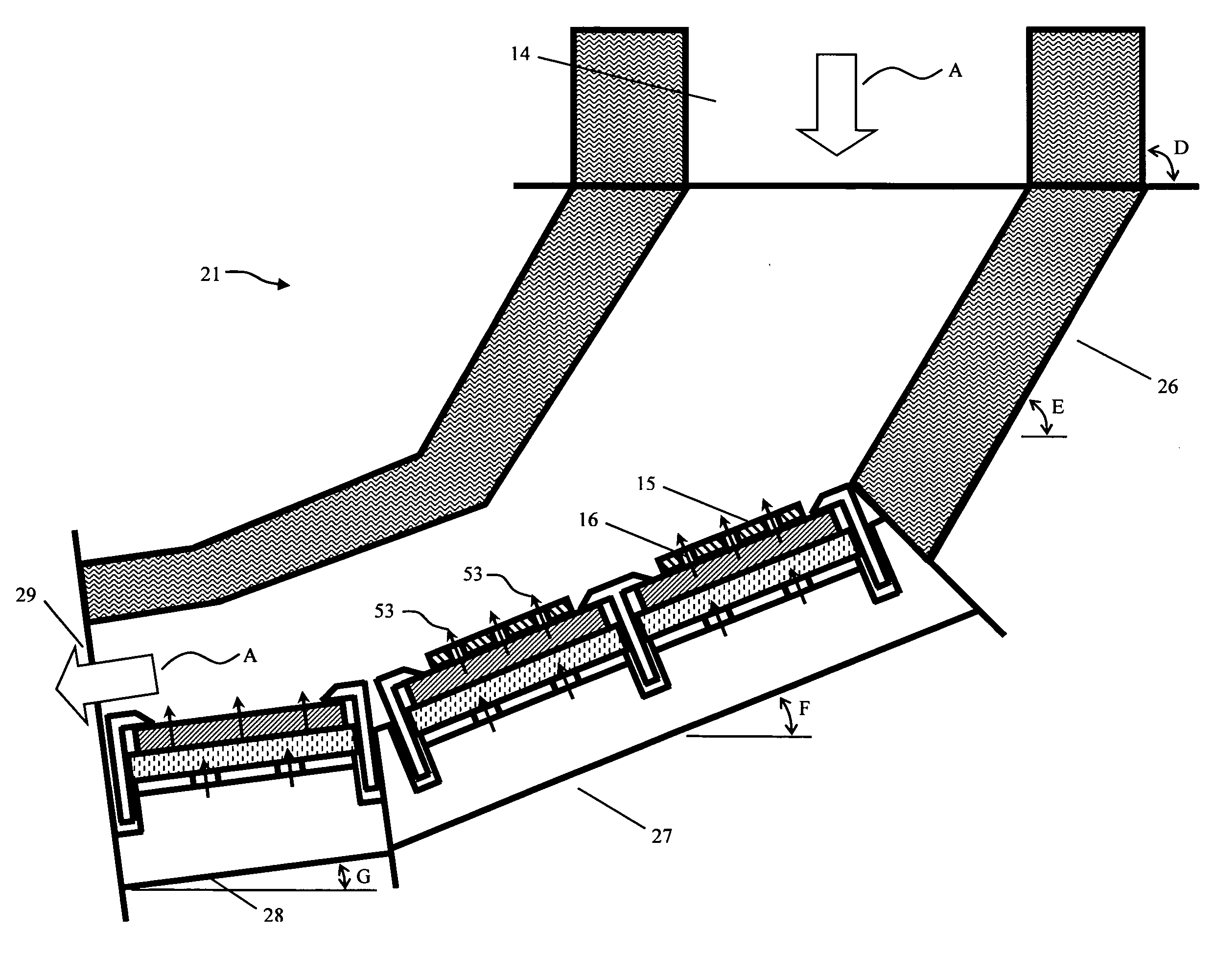
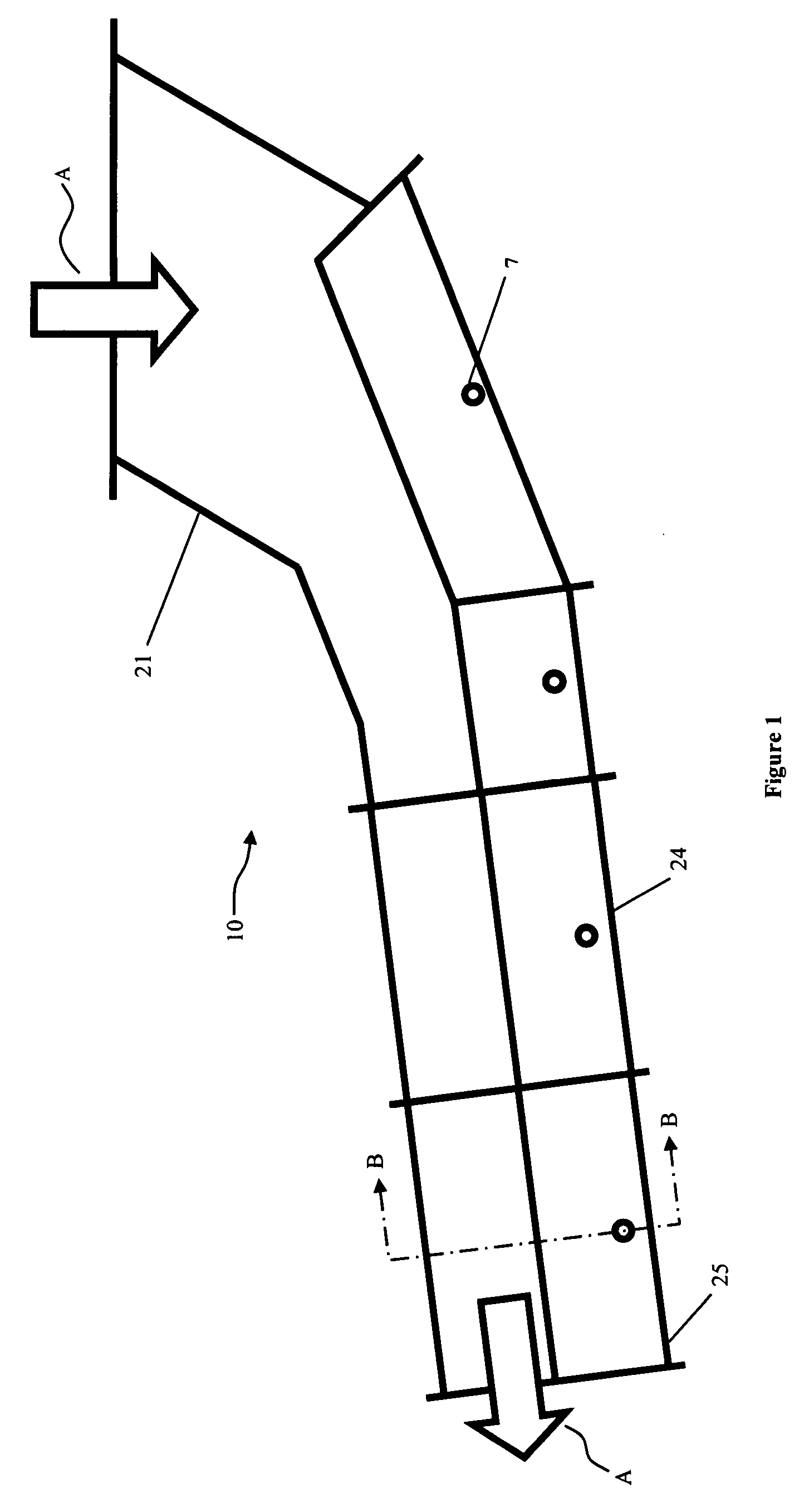
[0016]FIG. 1 depicts an external side view of a fluidizing gravity conveyer according to the present invention that comprises a conduit generally indicated at 10 for conveying hot, finely divided dry material such as preheated cement raw meal. As used herein, the term “hot material” will mean material in excess of 500° F. and in particular material in excess of 1200° F. Conduit 10 has material inlet 22 and material outlet 23 from which material is transferred to another apparatus in the industrial process such as a storage bin or another conveying device. The direction of material flow into and out of the conveyor is depicted by arrows A. Also depicted is separate material inlet section 21, the length of which is exaggerated in comparison to the depicted overall length of conduit 10. Conduit 10 is preferably assembled as a series of attached sections, with substantially identical attached conveying sections 24 and 25 depicted. In practice, and of course depending upon the specific a...


PUM


Abstract

An apparatus for conveying fluidized high temperature finely divided dry material by gravity utilizes a multi-layered, gas permeable gas distributor member comprising (i) an upper layer a flat, rigid gas permeable, porous medium capable of withstanding temperatures up to about 2900° F. through which gas to fluidize the material will pass; (ii) a middle layer comprised of a gas permeable insulation material that maintains its physical integrity when exposed to temperature differentials ranging from about 500° F. to about 2900° F.; and (iii) a lower layer that supports the top and middle layers comprising a substantially flat plate having a plurality of openings therethrough through which fluidizing gas can pass.

Description

BACKGROUND OF THE INVENTION [0001]The present invention relates to a fluidizing gravity conveyor for conveying finely divided material in an inclined path, and, more particularly, deals with an apparatus adapted for the conveyance, by gravitational force, of such materials while at elevated temperatures and while in a state of fluidity induced by the passage of a gas, such as air, through the material. The invention further comprises a fluid distributor member having a conveying surface for use in such a conveyor, wherein the fluid distributor has substantially uniform gas-permeability and through which gas is passed from an underlying plenum chamber into the overlying finely divided material to fluidize the material so that it will flow by gravity downwardly along the gas-permeable surface. More particularly the invention comprises a fluidizing gravity conveyor for conveying finely divided material that is particularly designed for conveying high temperature material including mate...

Claims


Application Information

Patent Timeline
IPC IPC(8): B65G53/20F17C13/00
CPCB65G53/20B65G53/18
Inventor SALMENTO, JOHN S.BURYNSKI, JR., RAYMOND M.SCHRANTZ, JAMES R.
Owner FLSMIDTH AS
Learn More