Energy and Water Conservation in Cooling of Containers Containing Heated Products

a technology for heating products and containers, applied in indirect heat exchangers, lighting and heating apparatus, transportation and packaging, etc., can solve the problems of non-recoverable heat released to the atmosphere at the cooling tower, the amount of heat that can be recovered, and the entire system shut down, so as to reduce or conserve energy and water loss

Inactive Publication Date: 2009-01-01
STOKLEY VAN CAMP INC
View PDF22 Cites 2 Cited by
  • Summary
  • Abstract
  • Description
  • Claims
  • Application Information

AI Technical Summary

Benefits of technology

[0012]The present invention provides a process that substantially reduces or eliminates the need for a cooling tower to provide a cooled water stream to cool heated products and the containers holding such heated products. Consequently, the present invention conserves energy and water lost by windage, evaporation and blow-off. The product, by way of example but not limitation, can be a food product, such as a beverage.
[0015]It will be appreciated by those skilled in the art that the system and methods disclosed here can be particularly suitable for the cooling of beverages and their respective containers after such beverages. Thus, the systems and methods disclosed here can be used in the reduction or elimination of undesirable reactions, such as chemical reaction, biochemical reaction, enzymatic reaction, and microbial reaction, and any combination thereof. By way of example, but not limitation, the systems and methods disclosed here can be used to reduce microbial load and the reactions or effects due to such microbial load and achieve desired shelf life.

Problems solved by technology

When filling of containers must be stopped for some reason, such as a temporary mechanical failure of filling equipment, it is undesirable to shut the entire system 100 down because it would take too long a time to start the entire system 100 again and get the temperatures of the various streams back to their desired levels.
The low spray water discharge temperature limits the amount of heat that can be recovered and used in upstream heating processes, and non-recovered heat is released to the atmosphere at the cooling tower.

Method used


Image

  • Energy and Water Conservation in Cooling of Containers Containing Heated Products
  • Energy and Water Conservation in Cooling of Containers Containing Heated Products
  • Energy and Water Conservation in Cooling of Containers Containing Heated Products

Examples


example 1

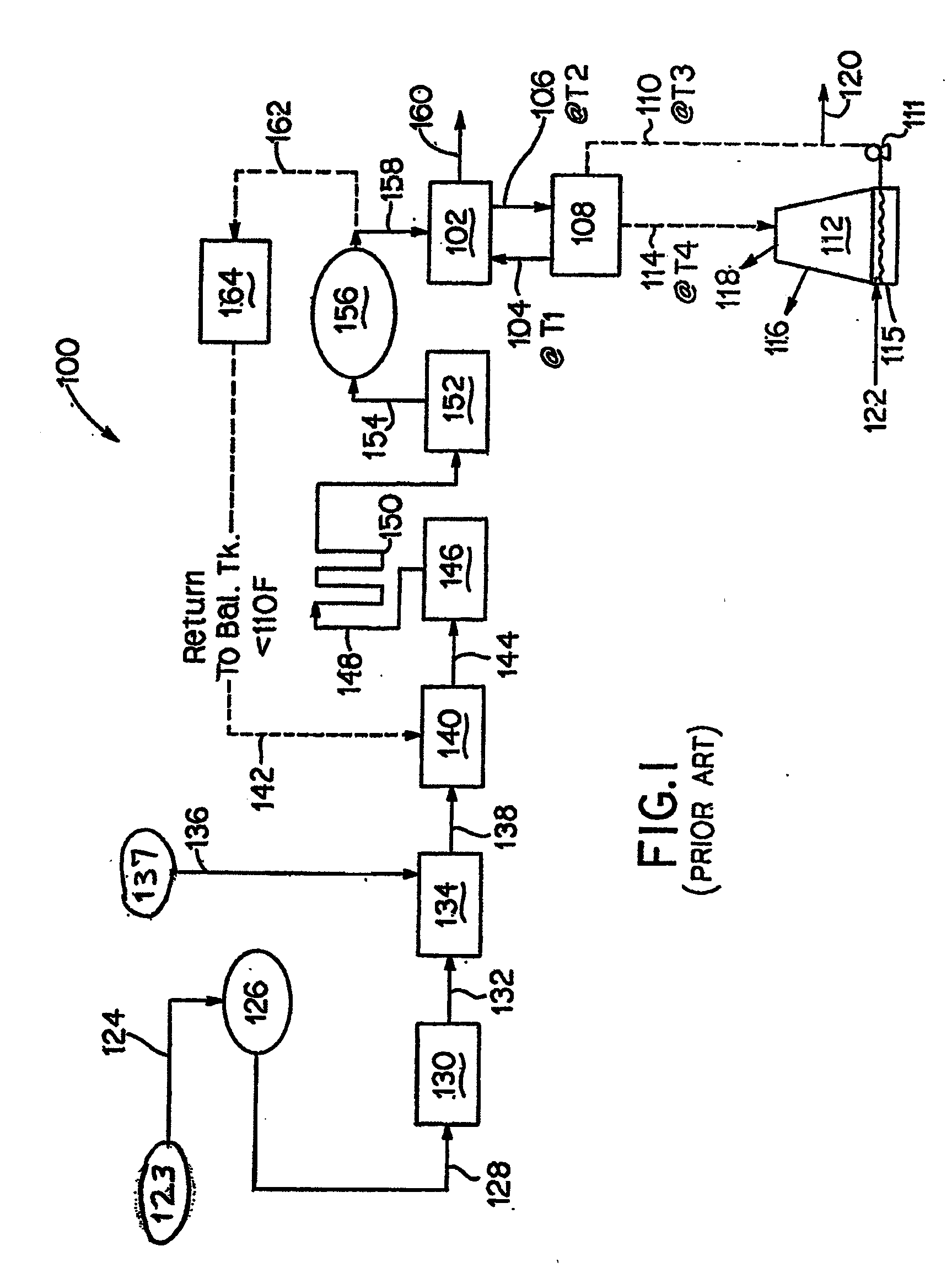
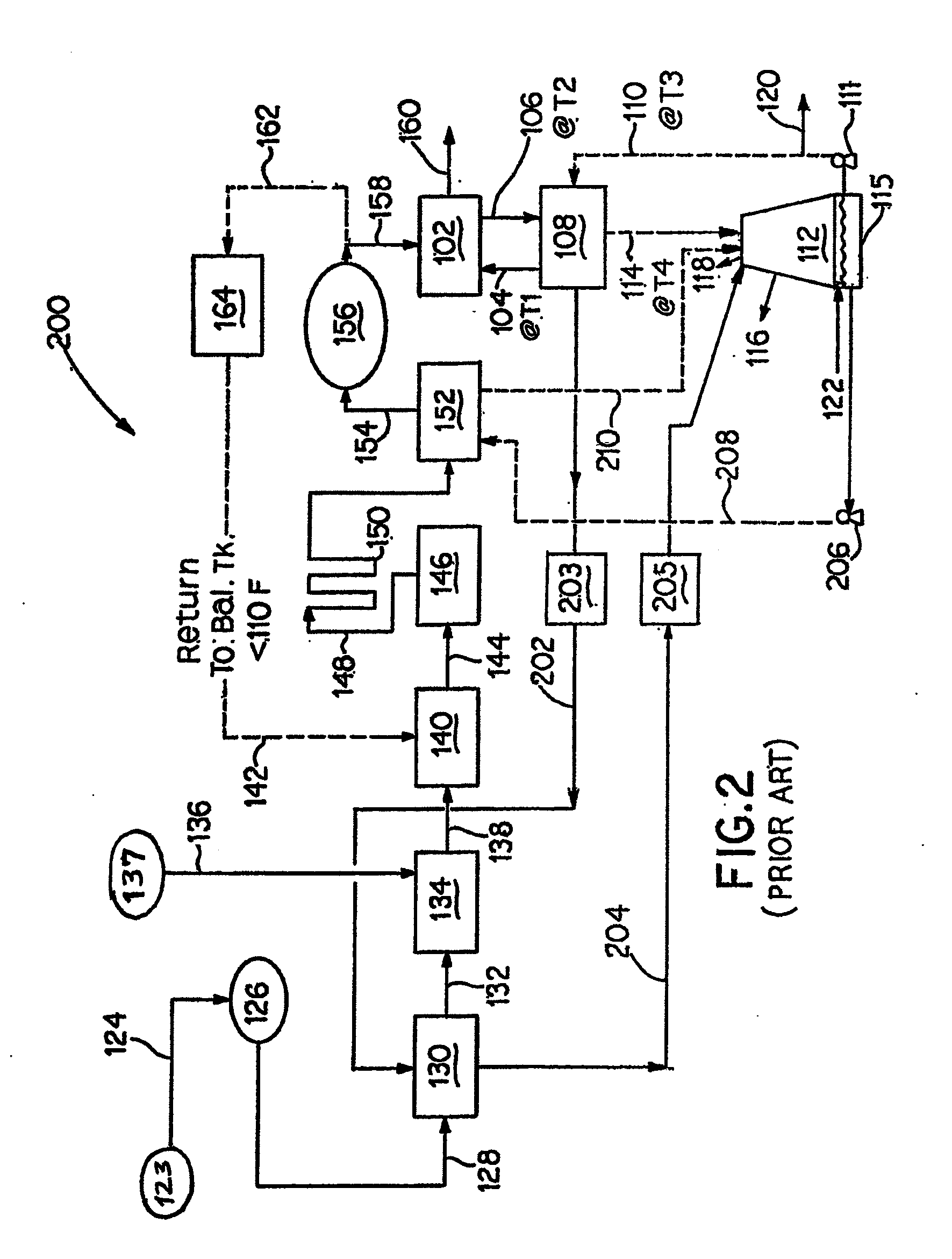
[0034]FIG. 4 depicts the flow rates and temperatures calculated for a nine zone container cooler, with only zones 1, 2, 8, and 9 (zones Z1 through Z9) in a conventional system 100 or 200 as shown in FIG. 1 or 2. Stream 158 comprising bottles 105 containing a beverage having a temperature of 185° F. is shown entering container cooler 102, and exiting container cooler 102 as stream 160 comprising bottles 105 containing the beverage having a temperature of 97.5° F.

[0035]Table 1 depicts calculated parameters with respect to a counter current container cooler or bottle cooler 102, when a conventional system as illustrated in FIG. 1 or FIG. 2 is used. In this example, counter current bottle cooler 102 has nine (9) zones numbered Z1 through Z9. At zone 1, the heated and bottled beverages enter the counter current bottle container cooler 102, and are moved by a belt through the successive numbered zones, until the bottled beverages exit zone 9. At zone 9, the first water stream 104 depicted...

example 2

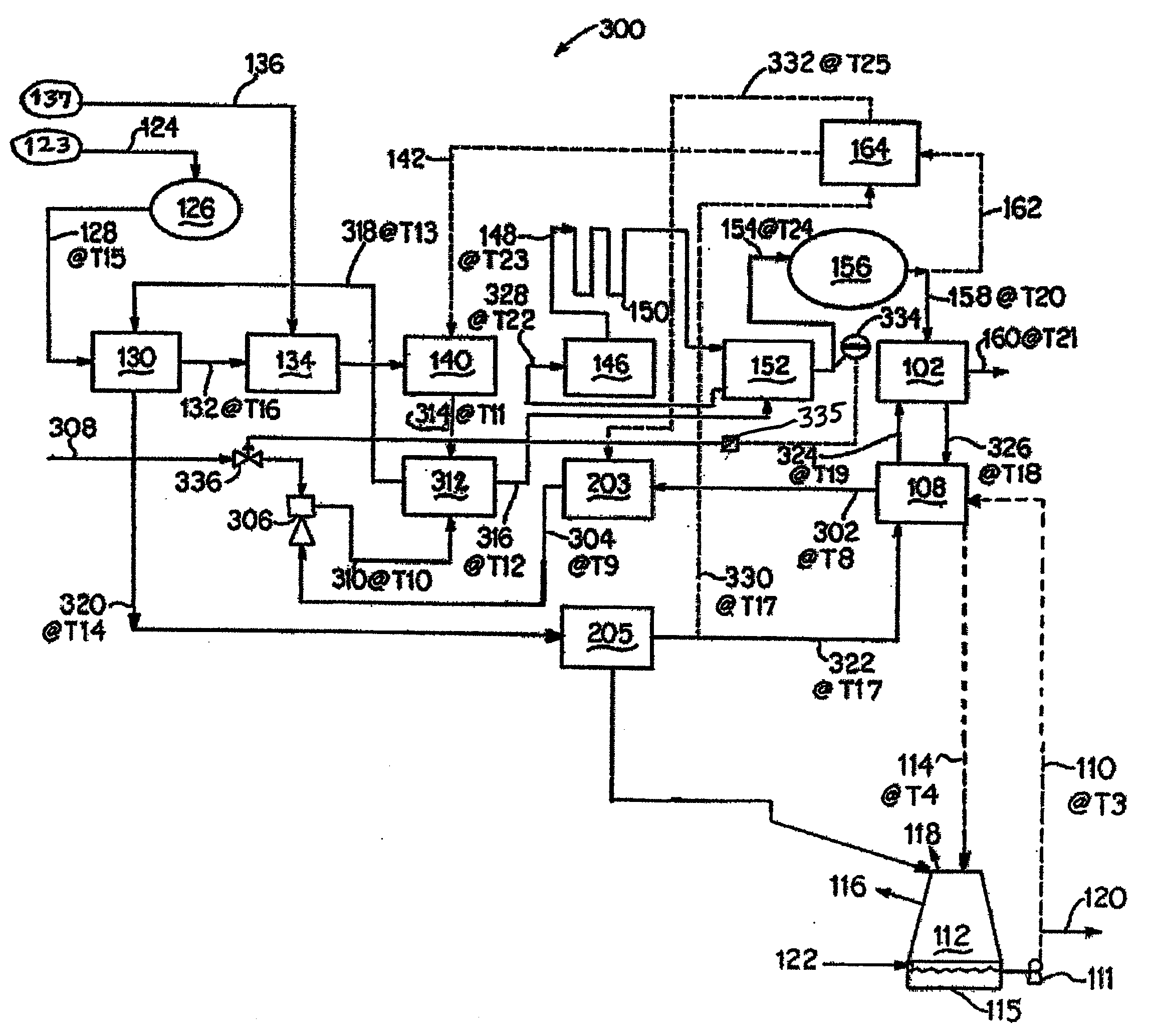
[0037]FIG. 5 depicts the flow rates and temperatures calculated for a nine zone container cooler, with only zones 1, 2, 8, and 9 (zones Z1 through Z9) depicted in a system 300 as shown in FIG. 3A.

[0038]Table 2 depicts calculated parameters with respect to a counter current container cooler or bottle cooler 102, when a system 300 is used as illustrated in FIG. 3A. In this example, counter current bottle cooler 102 has nine (9) zones numbered Z1 through Z9. At zone 1, the heated and bottled beverages enter the counter current bottle container cooler 102, and are moved by a belt through the successive numbered zones, until the bottled beverages exit zone 9. At zone 9, the stream 324 depicted in FIG. 3A enters current bottle container cooler 102, where it is sprayed over bottled beverages moving through zone 9, is then collected at the bottom of zone 9 and then routed to zone 8 where sprayed over bottled beverages moving through zone 8, etc., until the water stream exits bottle cooler 1...

embodiment 1

[0047]A system or apparatus comprising a chamber where a product stream is formed, a pre-heater located downstream of the chamber and upstream of a heater that heats the product stream to a desired temperature, the pre-heater comprising a circulating stream of a first heat transfer stream that pre-heats the food product, a container cooler comprising a circulating stream of a second heat transfer stream that cools containers containing the heated product coming out of the heater, and a heat exchanger where heat from the second heat transfer stream is transferred to the first heat transfer stream. The chamber can be any suitable structure wherein a product can be formed, including but not limited to a tank, a vessel, a nozzle, and / or a pipe. The product can be a food product.


PUM


Abstract

A system comprising a pre-heater located downstream of where a product stream is formed and upstream of a heater that heats the product stream to a desired temperature, the pre-heater comprising a circulating stream of a first heat transfer stream that pre-heats the food product, a container cooler comprising a circulating stream of a second heat transfer stream that cools containers containing the heated food product coming out of the heater, and a heat exchanger where heat from the second heat transfer stream is transferred to the first heat transfer stream. A method for using the system is also disclosed. The product can be a food product, including but not limited to a beverage. The container containing the heated product can be any suitable container, including but not limited to bottles and cans.

Description

FIELD OF THE INVENTION[0001]This invention relates to water and energy conservation in systems that require heating of a liquid for process considerations, such as a chemical, bio-chemical, enzymatic and or microbial reaction, filling the liquid in a container and subsequently cooling the filled container to a lower temperature for label application, storage or any other purpose. The heated liquid may be a food product, including, but not limited to, heated beverages that are placed in containers. The invention is illustrated for cooling of beverage containers containing heated beverages, but the disclosure herein encompasses cooling of containers containing heated non-beverages and similar processes.BACKGROUND[0002]Beverages frequently need to be heated to reduce microbial load and achieve desired shelf life. These beverages have to be further filled hot into containers (e.g., container made from polyethylene terephthalate (PET), or glass bottles and / or aluminum cans) and sealed so...

Claims


Application Information

Patent Timeline
Patent Type & Authority Applications(United States)
IPC IPC(8): A23L3/00F28D15/00
CPCA23L3/16A23L3/362F28D2021/0019F28D21/00F28C2001/006
Inventor DHRUV, ASHOKWU, REI-YOUNG AMOS
Owner STOKLEY VAN CAMP INC
Why Eureka
Try Eureka