Ultrasonic probe and inspection apparatus equipped with the ultrasonic probe

a technology of ultrasonic probe and inspection apparatus, which is applied in the direction of tomography, applications, instruments, etc., can solve the problems of affecting the satisfaction of the demand by itself, and the difficulty of fabricating the ultrasonic prob

Inactive Publication Date: 2009-01-01
CANON KK
View PDF14 Cites 116 Cited by
  • Summary
  • Abstract
  • Description
  • Claims
  • Application Information

AI Technical Summary

Benefits of technology

[0021]The present invention provides a novel ultrasonic probe which is optimum for taking an image of the internal structure of an inspection target by utilizing a photoacoustic effect, and also provides an inspection apparatus employing the ultrasonic probe.

Problems solved by technology

However, the PAT technique has the problem that, despite a demand for irradiating light to an inspection target from a position as close as possible to the target, the ultrasonic probe serving as a receiving unit impedes satisfaction of the demand by itself.
Also, when the ultrasonic probe having the structure of FIG. 11 is used with a capacitive micromachined ultrasonic transducer (CMUT) using a silicon substrate, which is described in U.S. Pat. No. 5,619,476, it is difficult to fabricate the ultrasonic probe due to the necessity of boring a through hole in the silicon substrate.

Method used


Image

  • Ultrasonic probe and inspection apparatus equipped with the ultrasonic probe
  • Ultrasonic probe and inspection apparatus equipped with the ultrasonic probe
  • Ultrasonic probe and inspection apparatus equipped with the ultrasonic probe

Examples


first exemplary embodiment

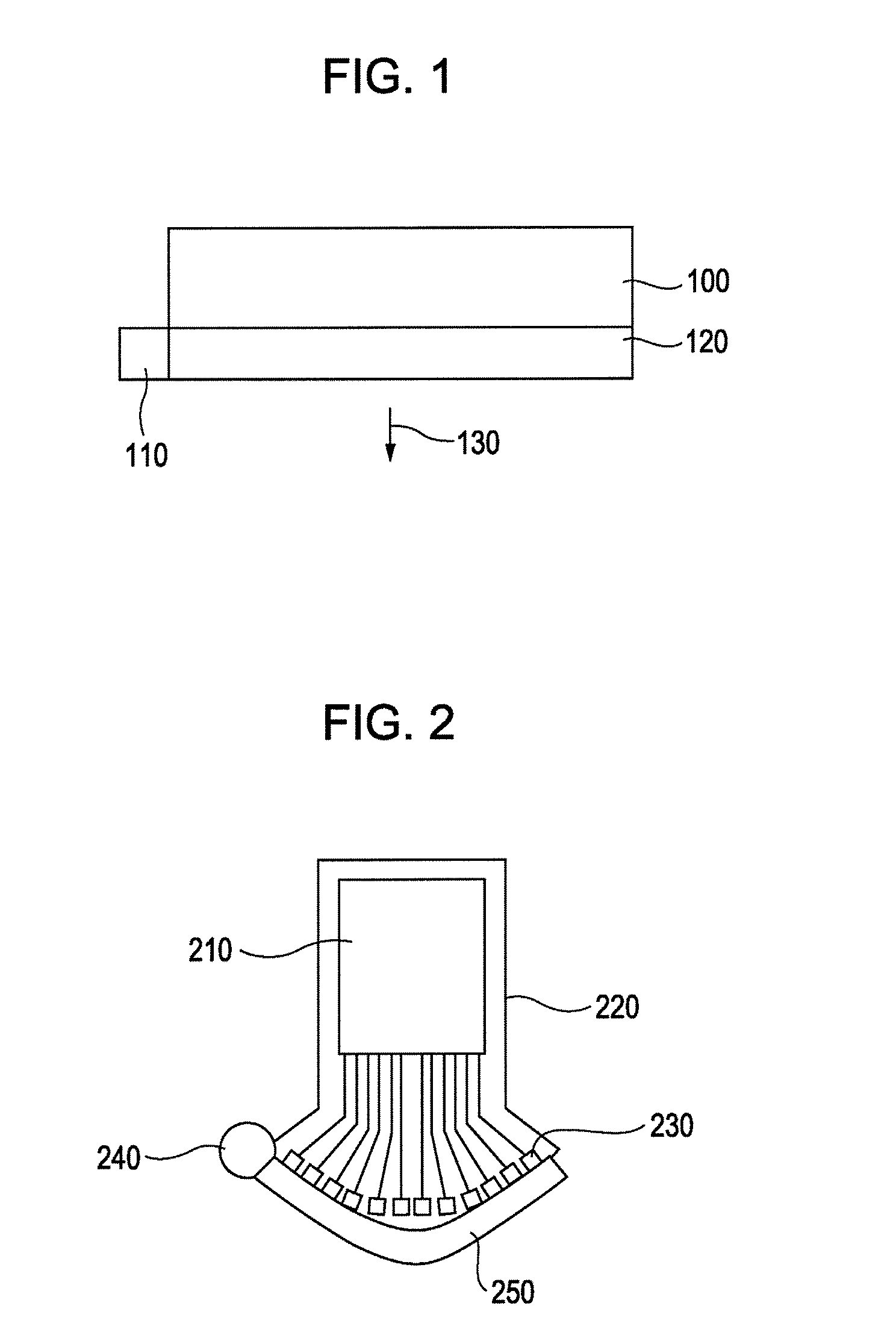
[0041]An ultrasonic probe according to a first exemplary embodiment of the present invention will be described with reference to FIG. 1.

[0042]In FIG. 1, numeral 100 denotes an ultrasonic probe, 110 denotes a light source, 120 denotes a diffusion plate for diffusing light, and 130 denotes an irradiated light.

[0043]More specifically, as shown in FIG. 1, the diffusion plate 120 for diffusing light is disposed on the ultrasonic receiving surface side, and the light is radiated through the diffusion plate 120 in a direction opposed to the direction in which ultrasonic transducing portions receive ultrasonic waves.

[0044]The present invention is intended to minimize a physical distance between an inspection target, e.g., a living body, and a light source and a physical distance between the inspection target and the ultrasonic probe, thus reducing attenuations of both the light radiated from the light source and the ultrasonic waves generated from the inside of the living body, which are ca...

second exemplary embodiment

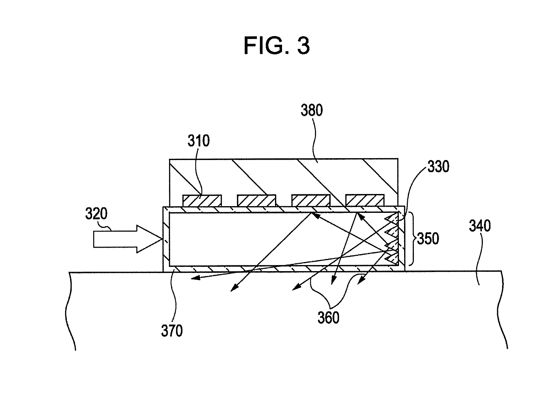
[0066]An ultrasonic probe according to a second exemplary embodiment of the present invention will be described with reference to FIG. 3. FIG. 3 is a schematic sectional view illustrating the ultrasonic probe according to the second exemplary embodiment.

[0067]In FIG. 3, the ultrasonic probe comprises an ultrasonic transducing portion 310, such as a piezoelectric transducer or a CMUT, an input light (laser) 320 introduced from a light source, a scatterer 330, an inspection target 340, an end surface 350 of a light guide member 370, a laser beam 360, the light guide member 370, and a substrate 380 of the ultrasonic probe.

[0068]On one side of the substrate 380 of the ultrasonic probe, the ultrasonic transducing portions 310 are arranged in a two-dimensional array. For example, the substrate 380 has a 3-cm square shape, and each of the ultrasonic transducing portions 310 has a 0.5-mm square shape. Those ultrasonic transducing portions 310 are arranged at a pitch of 2 mm in each of the l...

third exemplary embodiment

[0072]An ultrasonic probe according to a third exemplary embodiment of the present invention will be described below with reference to FIGS. 4A and 4B. FIG. 4A is a sectional view of the ultrasonic probe according to the third exemplary embodiment, and FIG. 4B is a plan view.

[0073]On one side of a substrate 400 of the ultrasonic probe, ultrasonic transducing portions 401, such as piezoelectric transducers or CMUTs, are arranged in a two-dimensional array.

[0074]A light guide member 402 is disposed on a surface of the substrate 400 on the side including the ultrasonic transducing portions 401. Terminal ends 403 of optical fibers are fixed to opposite ends of the light guide member 402. The light guide member 402 contacts the inspection target 404 with an acoustic coupling member 405 interposed between them.

[0075]A light 406 having propagated through the optical fibers 403 is introduced into the light guide member 402 from the opposite ends thereof. The light 406 introduced into the li...


PUM

PropertyMeasurementUnit
reflectivityaaaaaaaaaa
particle sizeaaaaaaaaaa
velocityaaaaaaaaaa

Abstract

An ultrasonic probe includes a light irradiating portion configured to radiate light for generating ultrasonic waves from a light absorber, an ultrasonic transducing portion configured to transduce the ultrasonic waves to an electric signal, and a light guide member configured to introduce light from a light source to the light irradiating portion. A light irradiating region of the light irradiating portion is included within an ultrasonic receiving region of the ultrasonic transducing portion.

Description

BACKGROUND OF THE INVENTION[0001]1. Field of the Invention[0002]The present invention relates to an ultrasonic probe suitable for use in an inspection utilizing a photoacoustic effect, and also relates to an inspection apparatus equipped with the ultrasonic probe.[0003]2. Description of the Related Art[0004]An inspection apparatus capable of obtaining a tomographic image or a three-dimensional image of a sample by utilizing a photoacoustic effect is proposed, for example, as described in U.S. Pat. No. 4,385,634. Such a technique is generally known as PhotoAcoustic Tomography and is called a “PAT technique”.[0005]A process of taking an image by the PAT technique is performed as follows:[0006]1) Light is irradiated to a sample from the exterior.[0007]2) The light propagates inside the sample.[0008]3) The light is absorbed by a portion inside the sample where a light absorption coefficient is large.[0009]4) The portion inside the sample is heated by the light absorption.[0010]5) The he...

Claims


Application Information

Patent Timeline
Patent Type & Authority Applications(United States)
IPC IPC(8): A61B8/00G01N29/34
CPCA61B5/0059A61B5/0095A61B5/742G01N2291/02475A61B5/72G01N29/2418A61B8/4416A61B8/4483A61B8/5261G01N2291/02466
Inventor NAGAE, KENICHIASAO, YASUFUMIFUKUTANI, KAZUHIKONAKAGAWA, KATSUMI
Owner CANON KK
Why Eureka
Try Eureka