Branched stent/graft and method of fabrication

a stent and graft technology, applied in the field of stents or graft devices delivered by intravascular catheters, can solve the problems of weak aneurysms bulging like balloons, low survival chances, and weak wall strength

Active Publication Date: 2009-01-01
ST JUDE MEDICAL CARDILOGY DIV INC
View PDF8 Cites 63 Cited by
  • Summary
  • Abstract
  • Description
  • Claims
  • Application Information

AI Technical Summary

Benefits of technology

[0019]As used herein the terms “filament” and “wire” are used interchangeably to describe strands of any suitable type of material including metal and non-metal materials used in aspects of the devices. As used herein, the term “braiding” includes interweaving where appropriate. It will be appreciated the term includes any braid or weave which enables elongation of the device with corresponding reduction in diameter so that the device may be delivered by vascular catheter.
[0020]One preferred method of fabrication includes braiding a plurality of highly elastic filaments supplied from a plurality of braiding spools onto an assembled two-piece or two-part mandrel. The filaments are braided onto a first part of the mandrel to form a first leg. The braiding is stopped and the braid is secured around the mandrel at the first leg distal end (last braided portion) using tape or other clamping means.
[0021]Long loops are formed from each filament exiting the tape / clamp above the distal end of the leg except for filaments that are intended to be the crotch or hinge filaments or wires connecting the legs. The filament loops created are made long enough to later be braided into the common body portion or trunk of the stent or graft. Once the loops are formed, they are coiled or spooled and secured to be out of the way so as not to become entangled in continued braiding. The loop end is taped / clamped to the mandrel on top of the loop starting point. The braiding process is restarted and a second leg is braided over a second part of the mandrel using the same plurality of filaments that were used to braid the first leg.
[0022]Once the second leg has been braided to a desired length, the filaments are taped / clamped to the mandrel and cut from the braiding spools. The braid and mandrel are removed from the braiding machine. The two parts of the two-piece assembled mandrel are separated and the legs and first and second mandrel parts are manipulated in relation to each other to position the legs adjacent each other connected by the hinge filaments. Next, a common body portion or trunk mandrel is attached using leg extensions designed to be inserted into the top of each leg mandrel. The loops that were formed and coiled or spooled are then made available for braiding the common body portion or trunk of the stent / graft.

Problems solved by technology

As the vessel tissues deteriorate, the vessel wall strength decreases, and the high blood pressure causes the aortic wall to stretch beyond its normal size, forming an aneurysm.
The weak aneurysm bulges like a balloon over time and can burst if the wall becomes too thin and weak to hold the blood pressure.
Once an AAA has ruptured, the chances of survival are low, with 80-90 percent of all ruptured aneurysms resulting in death.
AAA can be diagnosed from their symptoms when they occur, but this is often too late.
It has become apparent through use and clinical experience that the junctions of multiple stents or grafts presented placement problems of component alignment within the body.
The stents or grafts being independent of each other caused components to rub against each other causing metal fatigue and flow discontinuities or thrombosis could occur where one component was not aligned with another and protruded into the blood flow.
Use of multiple components also caused uneven vessel support such as where overlapping components may have an excess in vessel support as well as unsupported portions of the vessel where gaps occur between components.
In the case of grafts, gaps between components cause leaks and may result in continued blood pressure exposure to the aneurysm.
That design results in metal coverage gaps occurring at the outside top portion of each leg and the process requires the use of multiple braiding machines.

Method used


Image

  • Branched stent/graft and method of fabrication
  • Branched stent/graft and method of fabrication
  • Branched stent/graft and method of fabrication

Examples


first embodiment

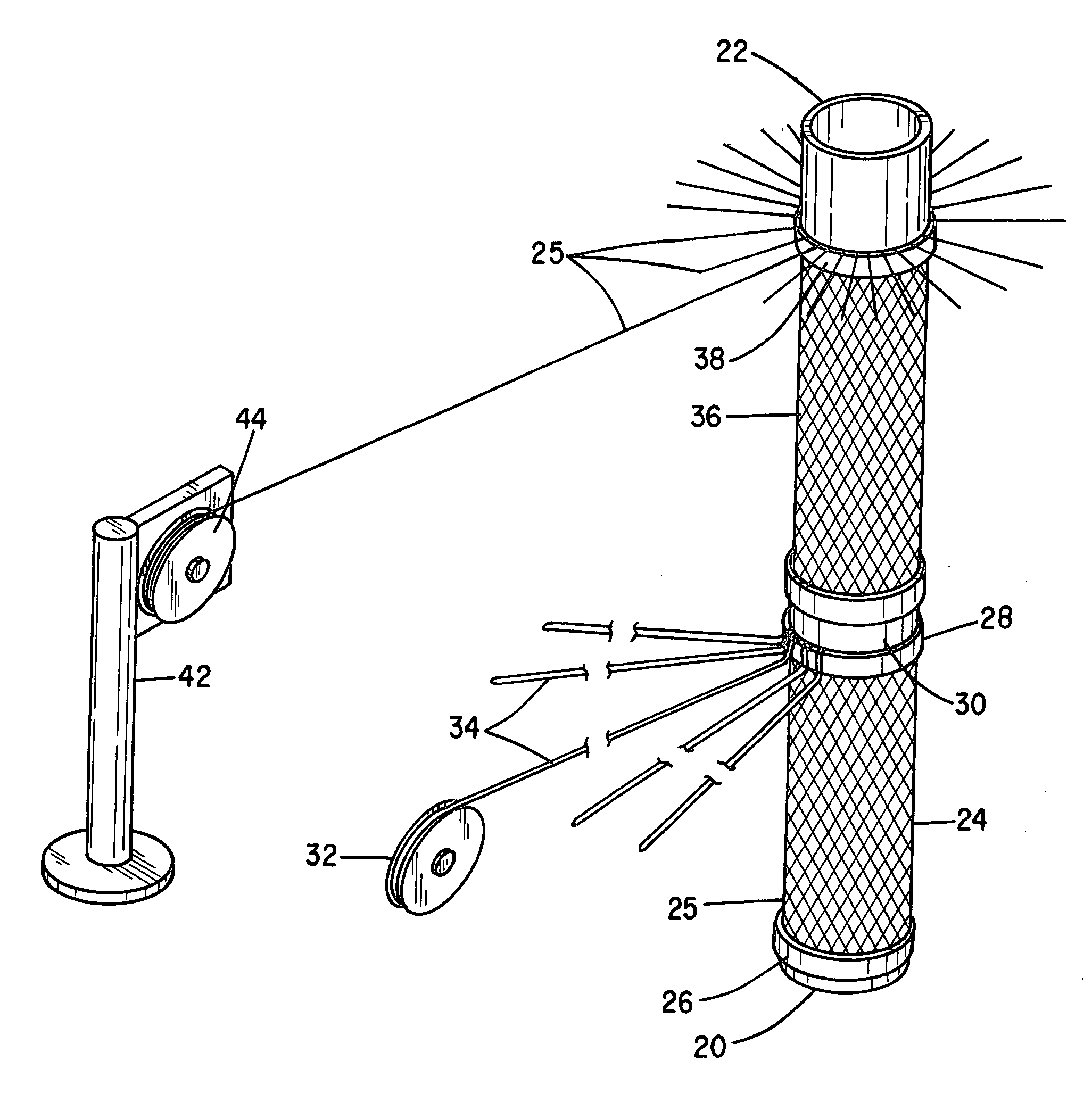
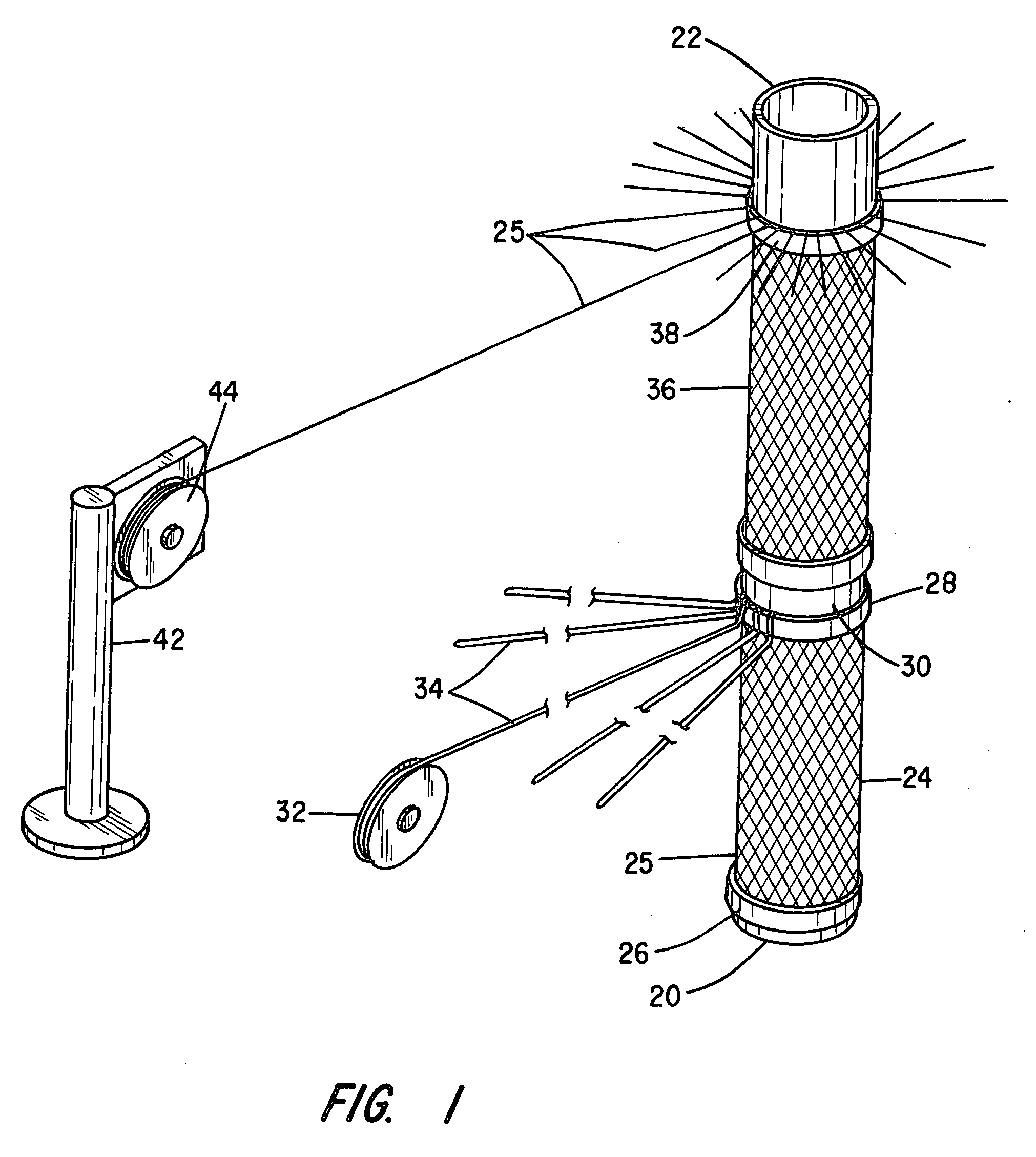
[0046]In a first embodiment, the distal ends of the wire loops are not cut or severed and each of the loops 34 is wound with the two wires together onto a spool for braiding the common body or trunk of the stent / graft using double strands. Thus, in the example, 28 spools of two filaments or wires each are available to be placed onto a braider that has at least 28 spool carriers.

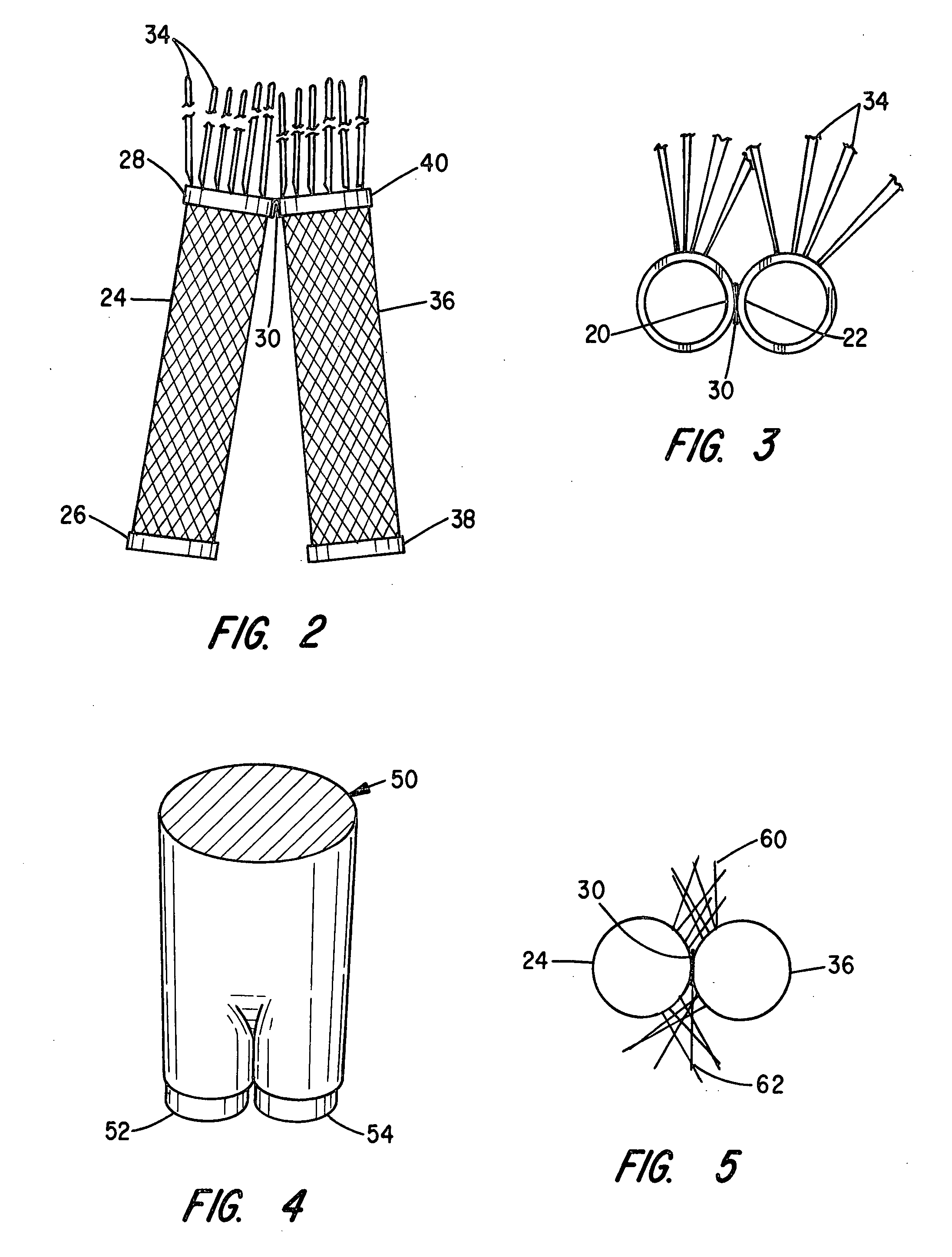
[0047]In an alternate embodiment, the wire loops are severed toward the ends to form two wires of substantially equal length from each original loop. The two wires are wound on separate spools for placement on a braider including at least (2 times 28) or 56 spool carriers.

[0048]FIG. 4 illustrates one shape of a mandrel at 50, which may be solid or hollow, for forming the common body or trunk of the stent or graft. There are two pilot diameters or leg extensions 52 and 54 for insertion into the corresponding two-leg mandrels. The now three-part mandrel is secured together by fasteners or other known means and ...

embodiment 80

[0051]In an alternative embodiment, the severed loops on 56 individual spools of wire are braided together over the trunk mandrel 50 in FIG. 4 for the length of the trunk shown in the embodiment 80 in FIG. 7 as 82. The braiding is then stopped and the wires are taped or clamped to the mandrel. The wires leading to the spools are cut and the mandrel assembly and braided device are removed from the braider. The finished device 80 has a trunk portion braided from single filaments or wires as is shown in FIG. 7.

[0052]In the embodiment with the loop braid, the final braiding of the trunk may be accomplished on the same original 32 carrier braider used for braiding the legs, but four of the spools, i.e., every 8th spool, would be empty. However, this would cause the final device to exhibit gaps between some of the braided wires. This is not as desirable as using a braider with the exact number of needed spool carriers. The gaps can be manually spaced more evenly prior to the final device ...


PUM


Abstract

Branched braided stent or graft devices and processes for fabrication of the devices are disclosed in which a trunk portion and two hinge leg portions are fabricated in one piece braided from a single plurality of filaments, whereby the legs contain the full plurality of filaments and the trunk portion contains a subset of the same plurality of filaments. The fabrication process involves braiding the hinged legs on a mandrel while retaining loops of filament between the hinged leg portions for subsequent braiding of the trunk portion of the stent or graft.

Description

BACKGROUND OF THE INVENTION[0001]I. Field of the Invention[0002]The present development relates generally to stent or graft devices for implantation in an anatomical structure and, more particularly, to intravascular catheter deliverable branched stent or graft devices and methods of fabrication. Embodiments include unique branched stent or graft devices for the treatment of abdominal aortic aneurysms (AAA) involving the aorta-iliac bifurcation by reinforcing, excluding, bridging, or lining the diseased vessel, and to methods of fabrication of such as stent or graft devices involving a unique braiding technique using a single plurality of filaments to form two hinged legs and the common body or trunk portion of the device.[0003]II. Related Art[0004]An aortic aneurysm is a weak area in the wall of the aorta, the main blood vessel that carries blood from the heart to the rest of the body. The aorta extends upwards from the heart in the chest and then arches downwards, traveling throug...

Claims


Application Information

Patent Timeline
Patent Type & Authority Applications(United States)
IPC IPC(8): A61F2/06A61F2/90
CPCA61F2/90A61F2002/065D04C1/06A61F2230/001A61F2/06D10B2509/06A61F2220/0075D04C3/48
Inventor ADAMS, DANIEL O.
Owner ST JUDE MEDICAL CARDILOGY DIV INC
Why Eureka
Try Eureka