Apparatus and Method for Fuel Flow Rate, Fuel Temperature, Fuel Droplet Size, and Burner Firing Rate Modulation

a technology of fuel flow rate and burner firing rate, which is applied in the direction of electric control, combustion types, instruments, etc., can solve the problem of loss of heat used to heat fuel

Inactive Publication Date: 2009-01-01
ECONOX TECH
View PDF19 Cites 23 Cited by
  • Summary
  • Abstract
  • Description
  • Claims
  • Application Information

AI Technical Summary

Benefits of technology

[0014]The apparatus and methods of the present invention employ fuel/heat interface surface areas that are large enough to allow the temperature at the fuel/heat interface to be maintained very near the desired final fuel temperature, thus pre...

Problems solved by technology

In these cases, some of the heat used to heat the fuel will ...

Method used


Image

  • Apparatus and Method for Fuel Flow Rate, Fuel Temperature, Fuel Droplet Size, and Burner Firing Rate Modulation
  • Apparatus and Method for Fuel Flow Rate, Fuel Temperature, Fuel Droplet Size, and Burner Firing Rate Modulation
  • Apparatus and Method for Fuel Flow Rate, Fuel Temperature, Fuel Droplet Size, and Burner Firing Rate Modulation

Examples


example 1

Gaseous Acetylene Fuel Flow Modulation Through Flash Heating

[0117]In this example the fuel combusted to cause a temperature increase in the air passing through the tube 305 described in FIG. 3 was acetylene. The non-heated fuel flow resulted in a large percentage of unburned fuel being exhausted. Incomplete combustion was indicated by heavy soot and black smoke coming out of the air out end 308 of the tube 305. When the “flash heating” fuel management techniques of this invention were used, however, combustion of the gaseous fuel was positively affected causing a more complete combustion.

[0118]This example differentiates the present invention from conventional devices that heat fuel to cause its vaporization because the fuel was in the gaseous state in both the complete and incomplete combustion situations. The underlying theory in the art regarding fuel vaporizing devices is that fuel in a vapor or gaseous state burns clean. Maximum combustion efficiency due to pre-heating the fuel...

example 2

Liquid Kerosene Fuel Flow Modulation by “Flash Heating”

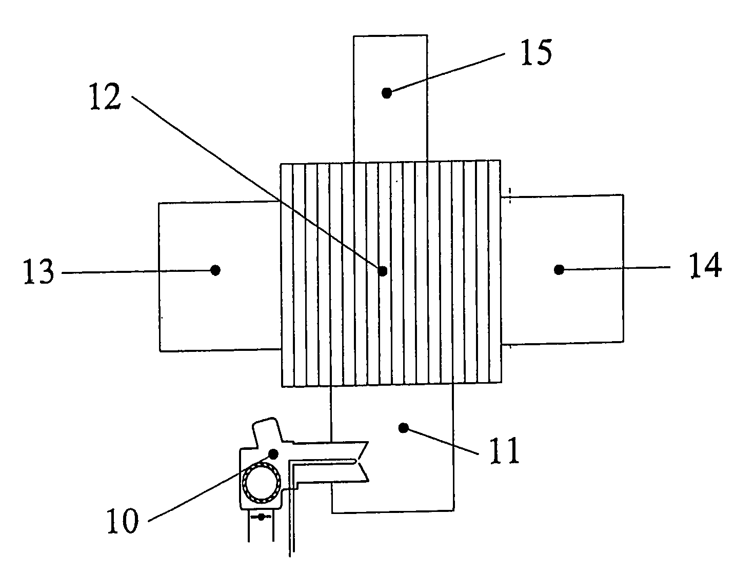
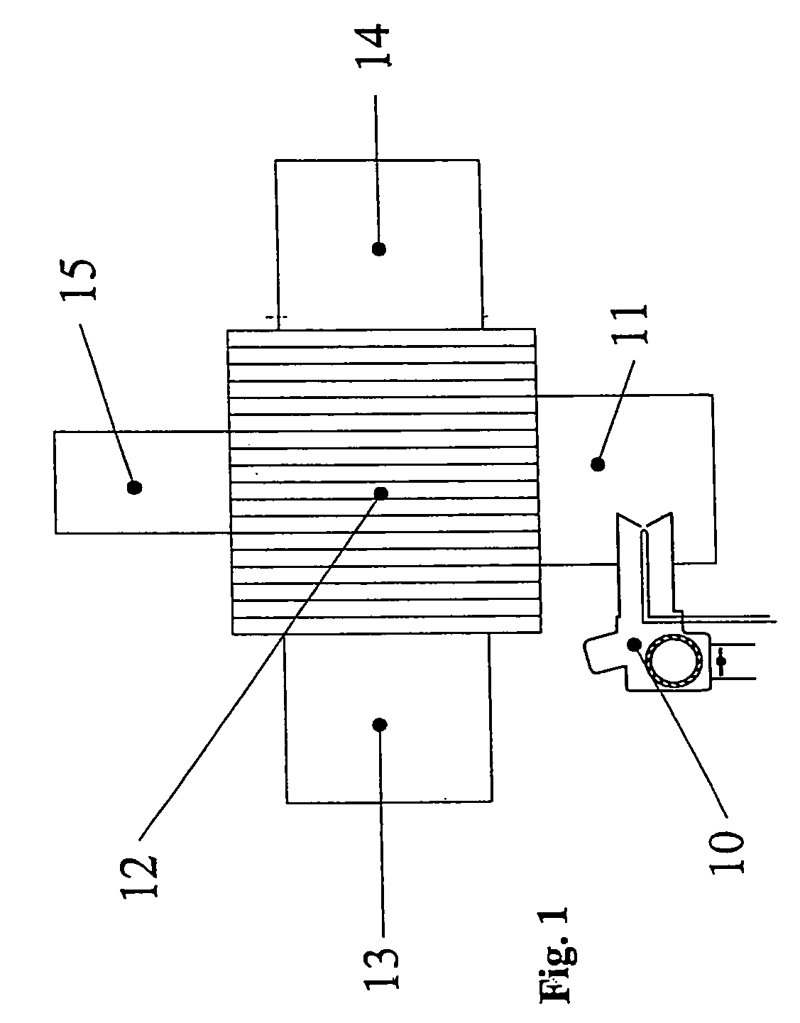
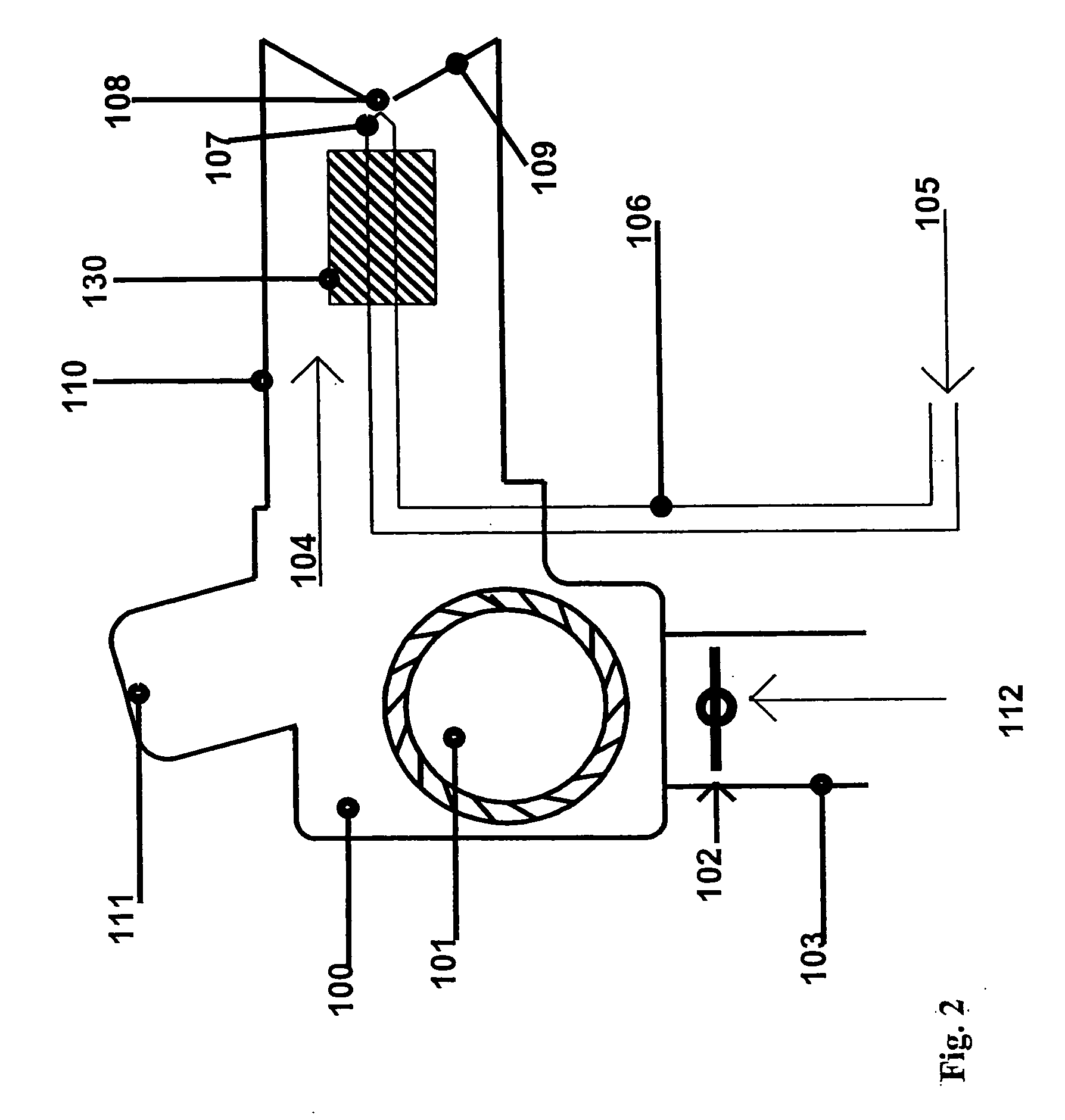
[0120]In this example the fuel combusted to cause a temperature increase in the air passing through the tube 305 described in FIG. 3 was kerosene. FIG. 6 shows the relationship between the temperatures to which the fuel was “flash heated” and the resultant fuel flow rates at a constant fuel pressure of 100 psi. FIG. 2 depicts how the “flash heating” modulation method was adapted to a conventional burner. FIG. 7 shows the relationship between the desired temperature rise of the fuel and the energy required to cause the fuel temperature and flow modulation. The electrical requirements can be used in algorithms used for remote monitoring where temperature rise of the fuel and electrical requirements to achieve the temperature rise are used to calculate fuel flow.

example 3

Liquid Kerosene Fuel Flow Modulation Through “Flash Heating”

[0121]This test simulated an operation regime in which the initial fuel flow is high and subsequently, after thermal stabilization, the fuel flow rate is modulated to a lower flow rate. FIG. 8 is a graphical representation of the data collected for fuel flow in gallons of fuel flowed per hour versus time during the test. FIG. 9 is a graphical representation of the temperature to which the fuel was modulated versus time elapsed. The fuel flow rate is shown to modulate when the fuel temperature is modulated. Time 14:30:00 to 14:48:00 in FIG. 9 indicates that the modulated flow rate is very stable.


PUM


Abstract

An apparatus and method for precisely, quickly and substantially uniformly controlling a combustion system by a transfer of heat to a fluidic fuel along a heat/fuel interface having a large surface area substantially immediately prior to the mixing of the fuel with air is provided. The control of the temperature of the fuel input to an air/fuel mixing region of the combustion system provides improved efficiency by an expansion of modulation ranges available for factors that together are determinative of the efficiency of combustion system operation such as fuel flow rate, fuel droplet size, air flow and input fuel pressure. In addition, the fuel/heat interface can be utilized as an in-line fuel flow meter for remote monitoring of the fuel flow rates and the prediction of problems in system functionality and future system failure time frames.

Description

[0001]This application claims priority from U.S. Provisional Application No. 60 / 753,671 entitled “Apparatus and Method for Fuel Flow Rate, Fuel Temperature, Fuel Droplet Size, and Burner Firing Rate Modulation” filed 22 Dec. 2005, the entire contents of which is incorporated herein by reference.FIELD OF THE INVENTION[0002]The present invention relates generally to apparatus and methods useful in connection with the combustion of liquid and / or gaseous fuels in a variety of applications. More particularly, the present invention is directed to apparatus and methods that employ “flash heating” fuel management and burner firing rate modulation techniques that provide improved combustion system efficiency, versatility, and robustness. As used herein “flash heating” refers to the utilization of large fuel / heat surface interfaces that allow fuels to be heated quickly and uniformly to predetermined temperature levels.BACKGROUND[0003]The complexity of the combustion process has lead to contra...

Claims


Application Information

Patent Timeline
IPC IPC(8): F02D45/00
CPCF02M31/18F23D11/001F23D11/448Y02T10/126F23D14/60F23D14/66F23N1/025F23D14/36Y02E20/34Y02T10/12
Inventor SCALIA, JR., WILLIAM H.
Owner ECONOX TECH
Why Eureka
Try Eureka