
Control Device for Vehicle, Control Method for Vehicle, and Method for Estimating Power Consumption of Cooling Fan

a technology for estimating power consumption and control devices, which is applied in the direction of engine cooling apparatus, electric control, engine controllers, etc., can solve the problem of not being able to control the operation of the internal combustion engine in an appropriate manner, and achieve the effect of accurately consuming power from the internal combustion engin

Inactive Publication Date: 2009-01-08
TOYOTA JIDOSHA KK
View PDF25 Cites 14 Cited by
  • Summary
  • Abstract
  • Description
  • Claims
  • Application Information

AI Technical Summary

Benefits of technology

[0004]The control device for a vehicle and the method for estimating the power consumption of a cooling fan according to the present invention take it as one of their objects to estimate the power consumption of a cooling fan of a cooling device, the cooling fan being one auxiliary unit which consumes power from the internal combustion engine, in a more accurate manner. Furthermore, the control device for a vehicle according to the present invention takes it as one of its objects to estimate the power consumption of an auxiliary unit which consumes power from the internal combustion engine more accurately, thus performing control of the operation of the internal combustion engine in a more appropriate manner. Moreover, the control device for a vehicle according to the present invention takes it as one of its objects to estimate the power consumption of an auxiliary unit which consumes power from the internal combustion engine more accurately, thus performing control of the starting of the internal combustion engine in a more appropriate manner.
[0008]With this first aspect of the present invention, there may be included an engine side rotational speed detection means which detects the rotational speed of the fluid coupling on the side of the internal combustion engine. Furthermore, it would also be acceptable to arrange for the power consumption estimation means to be a means which estimates the power consumption of the cooling fan, based upon the rotational speed on the side of the cooling fan which has been detected, and upon the rotational speed on the side of the internal combustion engine which has been detected. If this is done, it is possible to estimate the power consumption of the cooling fan yet more accurately.
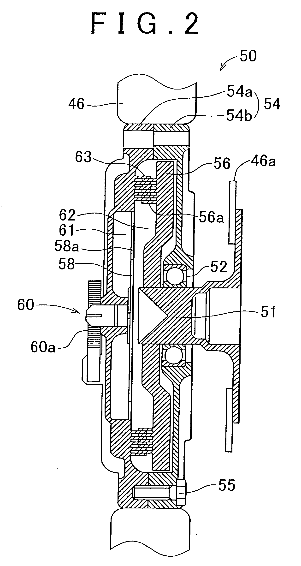
[0010]With this second aspect of the present invention, in a vehicle including an internal combustion engine and a cooling device including a cooling fan used for cooling of a device the cooling fan being one auxiliary unit which is driven along with consuming power from the internal combustion engine, and a fluid coupling which, along with adjusting the amount of a viscous fluid which is supplied to a power transmission unit, also transmits power from the internal combustion engine to the cooling fan, the power consumption of the cooling fan is estimated, based upon the rotational speed on the side of the internal combustion engine, and upon the state of the fluid coupling. Due to this, it is based upon the fact that the state of the fluid coupling exerts a great influence upon the power consumption of the cooling fan. Because of this, it is possible to estimate the power consumption of the cooling fan more accurately.
[0020]And, with this third aspect of the present invention, it would also be acceptable to include a storage means for storing data, and for the state estimation means to include an engine side rotational speed detection means which detects the rotational speed of the fluid coupling on the side of the internal combustion engine, and a fan side rotational speed detection means which detects the rotational speed of the fluid coupling on the side of the cooling fan, and to be a means which, along with estimating the state of the fluid coupling based upon the rotational speed on the side of the internal combustion engine, and upon the rotational speed on the side of the cooling fan, which have been detected during operation of the internal combustion engine, also stores the estimated state of the fluid coupling in the storage means. Moreover, it would also be acceptable to arrange for the fluid coupling to be so adapted that the amount of the viscous fluid which is supplied to the power transmission unit is adjusted according to the temperature of the device, and for the state estimation means to include a temperature detection means which detects the temperature of the device, and to be a means which estimates the state of the fluid coupling based upon the temperature which has been detected. If this is done, it is possible to estimate the state of the fluid coupling in a more accurate manner.

Problems solved by technology

As a result, sometimes it happens that it becomes impossible to control the operation of the internal combustion engine in an appropriate manner, which is undesirable.

Method used


Image

  • Control Device for Vehicle, Control Method for Vehicle, and Method for Estimating Power Consumption of Cooling Fan
  • Control Device for Vehicle, Control Method for Vehicle, and Method for Estimating Power Consumption of Cooling Fan
  • Control Device for Vehicle, Control Method for Vehicle, and Method for Estimating Power Consumption of Cooling Fan

Examples


Embodiment Construction

[0036]Next, the present invention will be explained, using a preferred embodiment of implementation thereof.

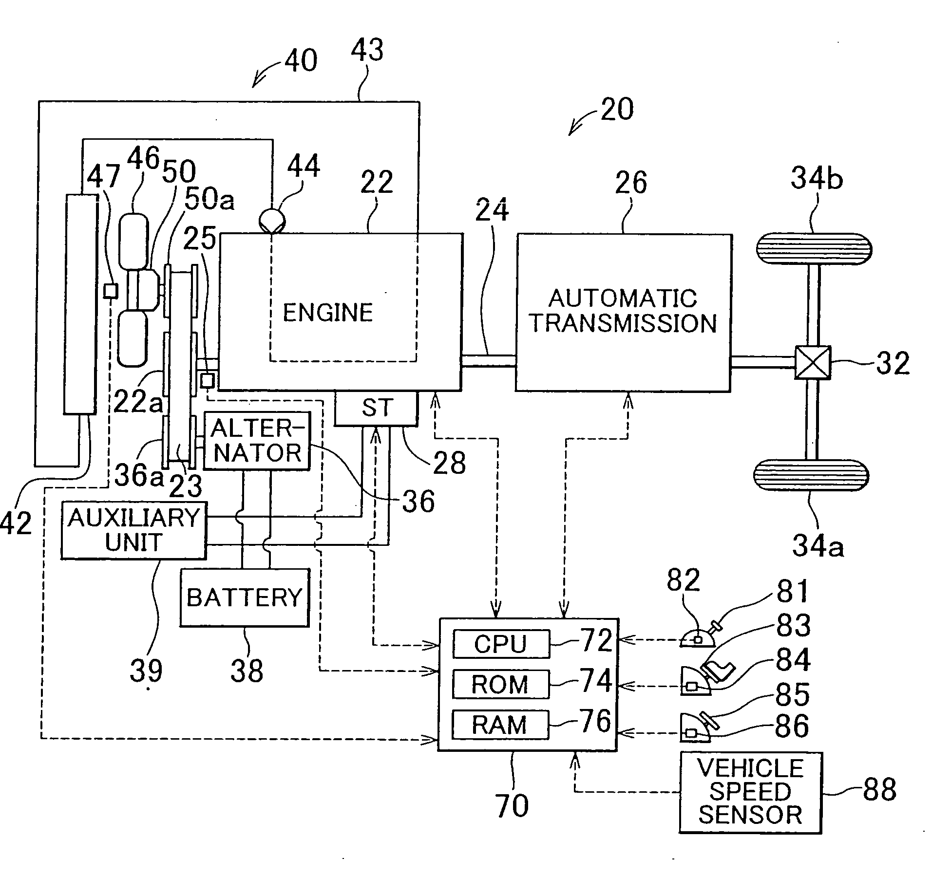
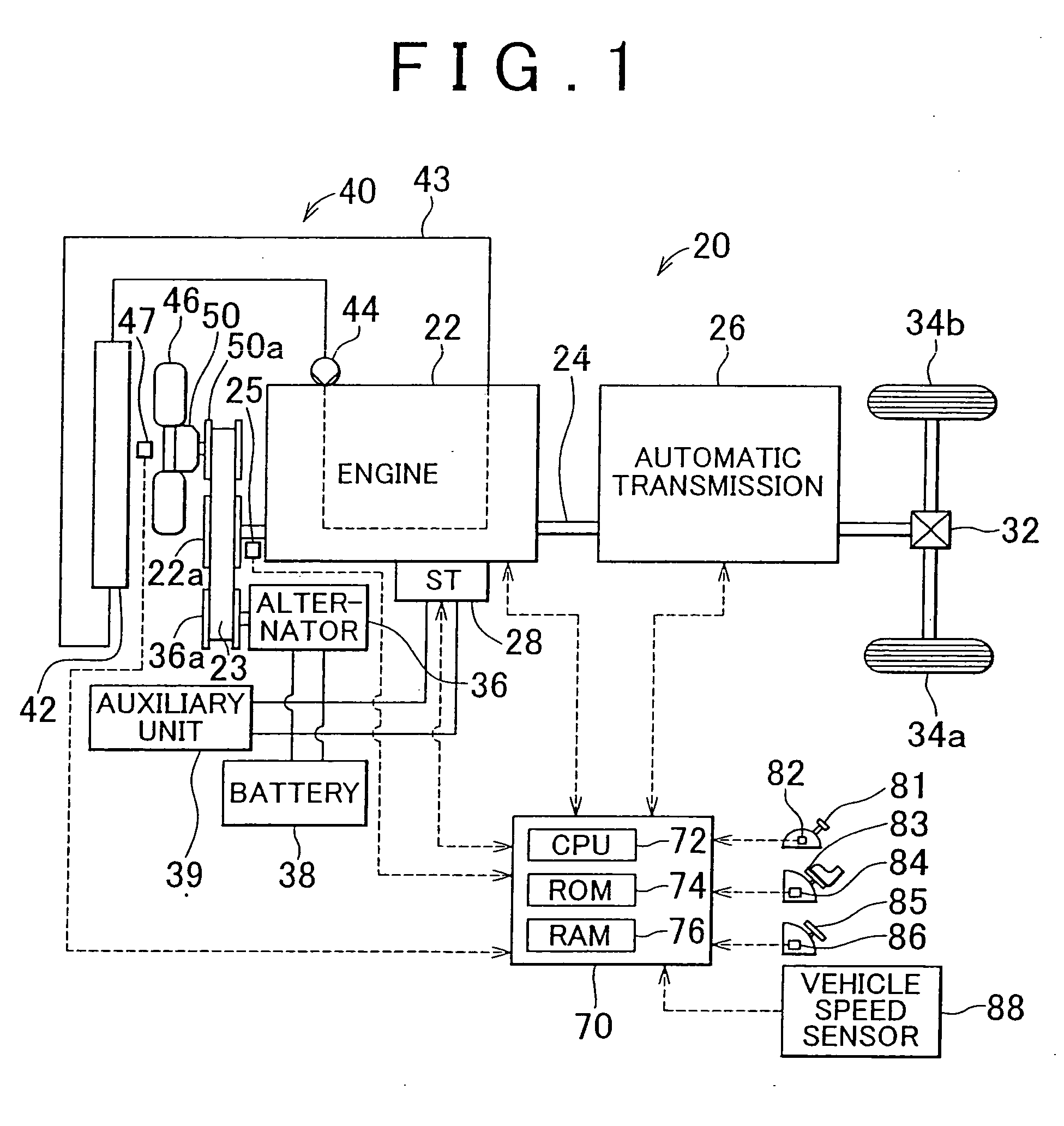
[0037]FIG. 1 is a structural diagram showing the schematic structure of a vehicle 20, as an embodiment of the present invention. As shown in the figure, this vehicle 20 of the embodiment comprises an engine 22, an automatic transmission 26, a starter motor 28 (shown in the figure as ST), an alternator 36, a battery 38, an auxiliary machine 39, a cooling device 40, and an electronic control unit 70. The engine 22 is an internal combustion engine which outputs power from a hydrocarbon type fuel such as gasoline or light oil or the like. The automatic transmission 26 changes the speed of power which is outputted from a crank shaft 24 of the engine 22 and transmits it to vehicle wheels 34a and 34b via a differential gear 32. The starter motor 28 is made to be capable of motoring the engine 22. The alternator 36 generates electricity using power from the engine 22. The battery 38 c...


PUM


Abstract

Along with a rotational speed sensor being fitted to the crank shaft of an engine, a rotational speed sensor is fitted to a cooling fan; and the energy consumption of the cooling fan is estimated by using a map based upon an engine rotational speed (a pulley rotational speed Np) and a fan rotational speed Nf which have been detected by these rotational speed sensors. By controlling the operation of the engine based upon the energy consumption of the cooling fan which has been estimated in this manner, it is possible to control the operation of the engine more appropriately.

Description

FIELD OF THE INVENTION[0001]The present invention relates to a control device for a vehicle which comprises an internal combustion engine, and a cooling device including a cooling fan used for cooling of a device the cooling fan being one auxiliary unit which is driven along with consuming power from the internal combustion engine, and a fluid coupling which, along with adjusting the amount of a viscous fluid which is supplied to a power transmission unit, also transmits power from the internal combustion engine to the cooling fan; and to a control method for such a vehicle, and to a method for estimating power consumption of a cooling fan.BACKGROUND OF THE INVENTION[0002]To connect a cooling fan which blows air at a radiator used for cooling an internal combustion engine which is mounted to a vehicle to the internal combustion engine via a fluid coupling is disclosed in Japanese Laid-Open Patent Publication Heisei 10-89386. In the structure of such a fluid coupling, a space within ...

Claims


Application Information

Patent Timeline
Patent Type & Authority Applications(United States)
IPC IPC(8): F01P7/02F01P7/08F02D29/02F02D45/00F02N19/00
CPCF01P7/042F02D11/10F02D41/021F02D41/062F02N2300/104F02D2200/1004F02D2250/18F02N19/00F02D41/083
Inventor MINEKAWA, HIDETO
Owner TOYOTA JIDOSHA KK
Learn More