
Automatic consumable and torch length detection via pressure decay

Active Publication Date: 2009-01-08
ILLINOIS TOOL WORKS INC
View PDF5 Cites 37 Cited by
  • Summary
  • Abstract
  • Description
  • Claims
  • Application Information

AI Technical Summary

Benefits of technology

[0004]It would therefore be desirable to have an apparatus and method capable of detecting the consumable type or length of tor

Problems solved by technology

However, an inexperienced or careless user may not properly set the levels for the type of consumable for the operation to be performed.
Additionally, when a different length of torch is installed on a plasma power source, a longer length of hose will cause a different pressure drop through the length of the torch than a shorter length of hose.
A user will typically not adjust a manually controlled gas system to an optimal level based on torch length.
Therefore cutting performance, arc stability, and consumable life may be less than optimal.

Method used


Image

  • Automatic consumable and torch length detection via pressure decay
  • Automatic consumable and torch length detection via pressure decay
  • Automatic consumable and torch length detection via pressure decay

Examples


Embodiment Construction

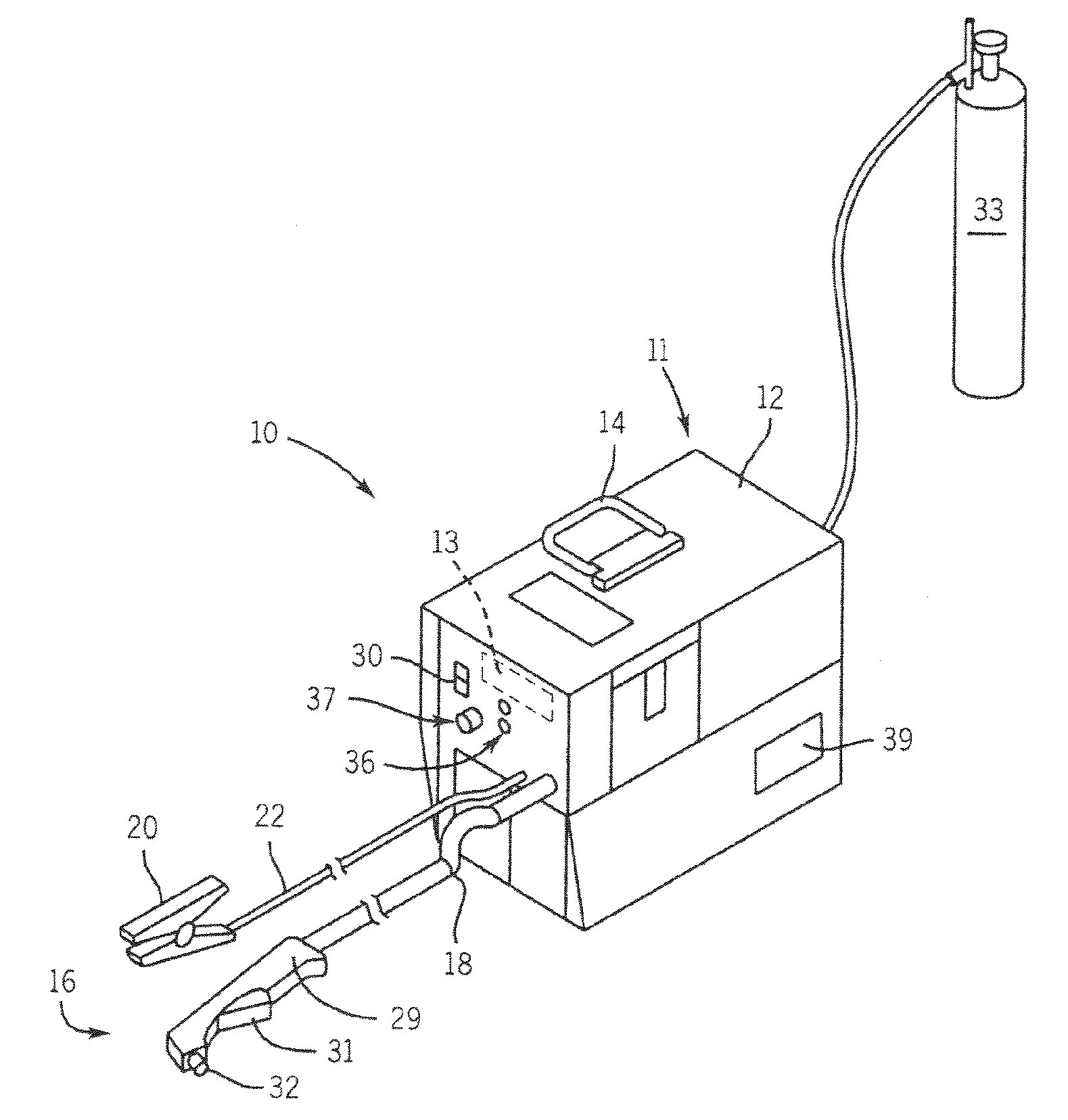
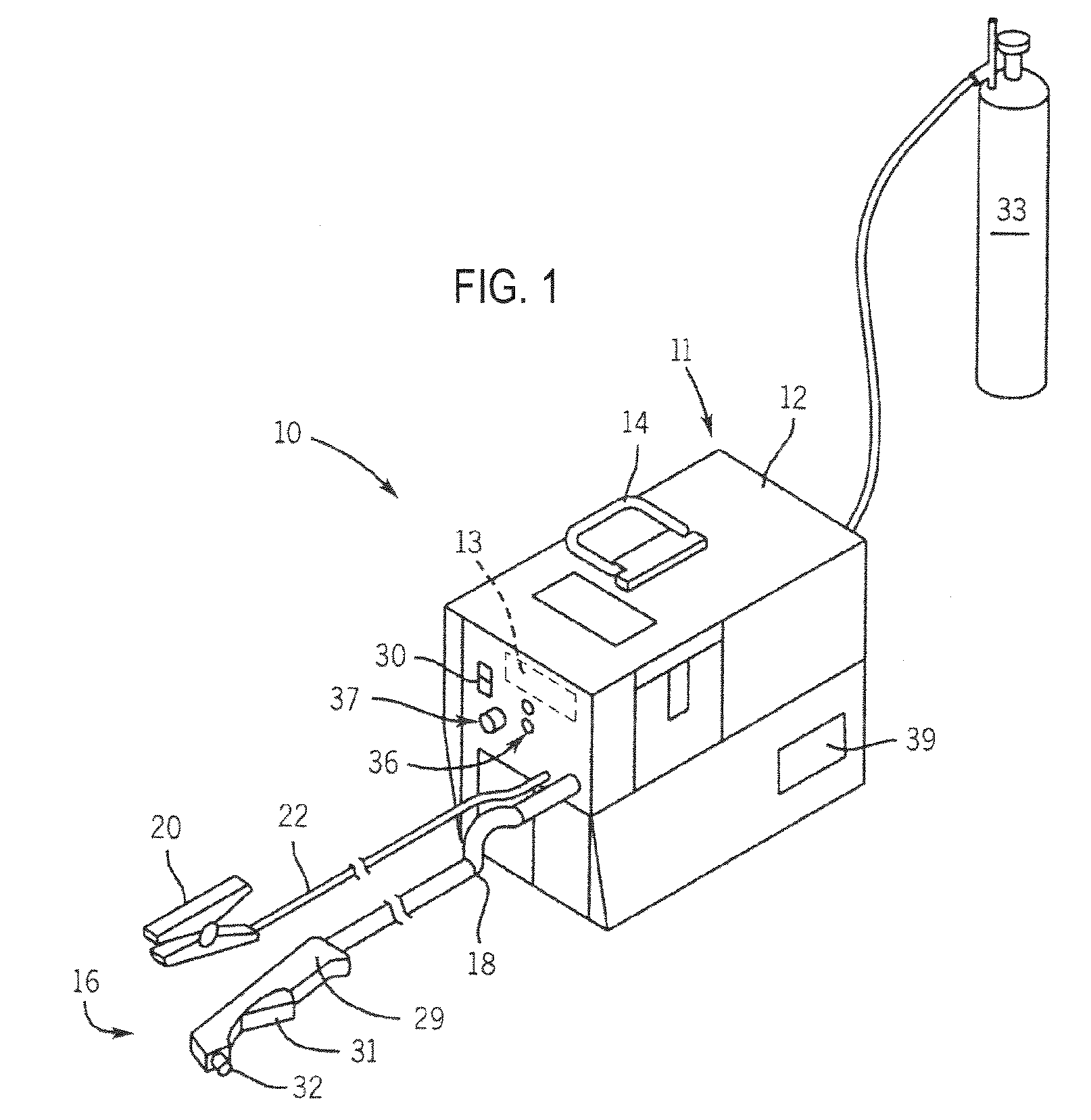
[0018]FIG. 1 shows a plasma cutting / gouging system 10 according to the present invention. Plasma cutting / gouging system 10 is a high voltage system with open circuit output voltages that typically range from approximately 230 Volts Direct Current (VDC) to over 300 VDC. Plasma cutting / gouging system 10 includes a power source 11 to condition raw power and generate a power signal suitable for plasma cutting / gouging applications, such as cutting and gouging. Power source 11 includes a housing 12. A controller 13 receives operational feedback and monitors the operation of plasma cutting / gouging system 10. Power source 11 includes a handle 14 to effectuate transportation from one site to another. Connected to power source 11 is a torch 16 including a cable 18 and a torch body 29. Cable 18 provides torch body 29 with power and compressed air or gas, and also serves as a communications link between torch body 29 and power source 11. Torch body 29 has a trigger 31 thereon and a work tip 32 ...


PUM

PropertyMeasurementUnit
Lengthaaaaaaaaaa
Pressureaaaaaaaaaa
Poweraaaaaaaaaa

Abstract

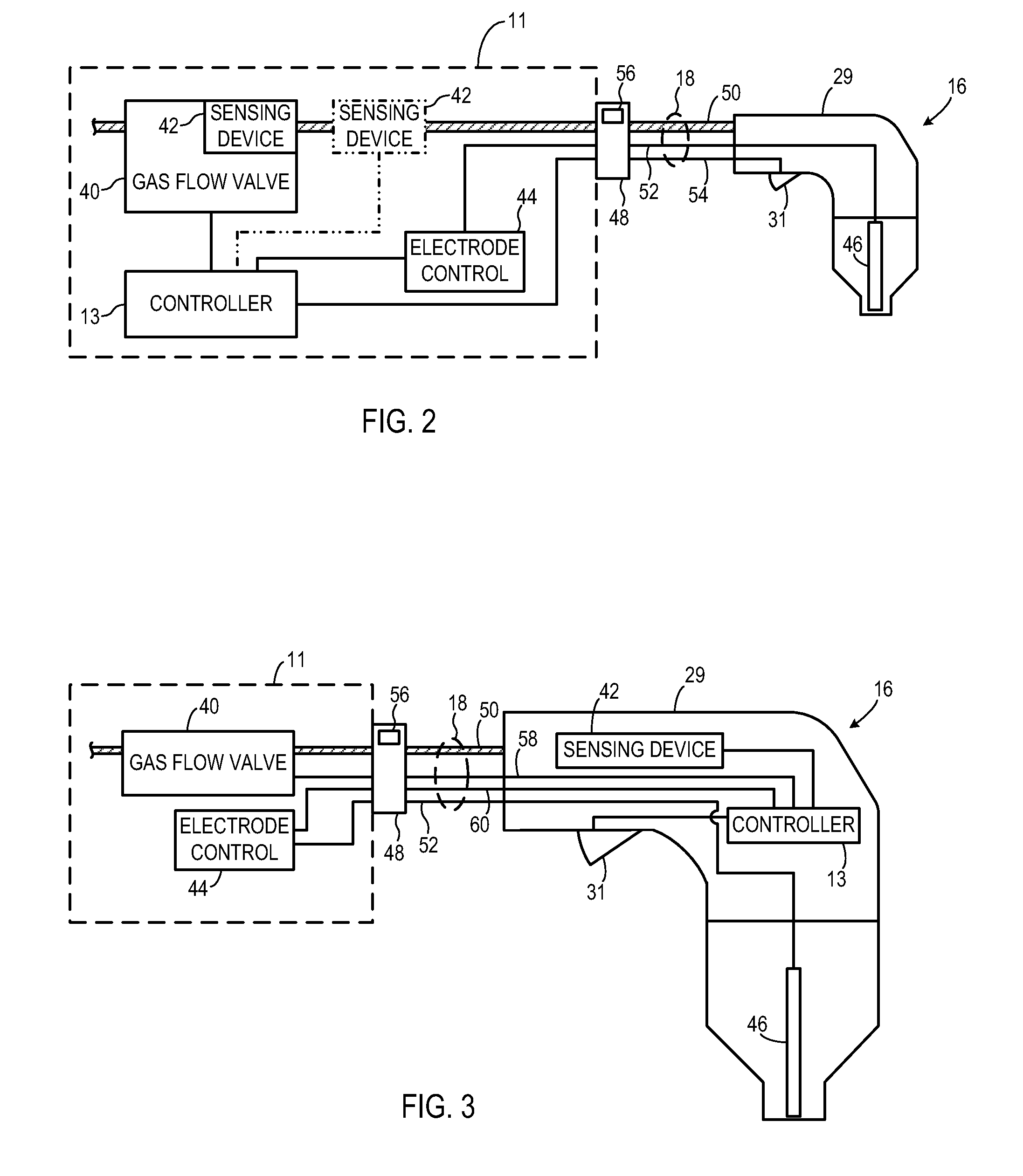
A system and method for a plasma system includes a plasma torch actuated by a trigger, a consumable installed in the plasma torch, and a gas flow system constructed to receive pressurized gas and provide a gas flow to the plasma torch. A gas flow regulating system is included and configured to regulate the gas flow, and a sensing device is included and configured to monitor a gas pressure in the plasma torch. The plasma system also includes a controller configured to receive a signal from the sensing device and to determine one of a length parameter of the plasma torch and a type of the consumable therefrom.

Description

CROSS-REFERENCE TO RELATED APPLICATION[0001]The present application is a non-provisional of, and claims priority to, U.S. Provisional Application Ser. No. 61 / 056,752, filed May 28, 2008, and is a continuation in part of and claims priority of U.S. patent application Ser. No. 11 / 460,446 filed Jul. 27, 2006, the disclosures of which is incorporated herein.BACKGROUND OF THE INVENTION[0002]The present invention relates generally to plasma cutting / gouging systems and, more particularly, to an apparatus and method for automatically detecting plasma cutting / gouging parameters via pressure decay. Typically, to perform a plasma cutting operation, a user must install the proper cutting consumables to the plasma torch, adjust the gas pressure supplied to the plasma torch, and adjust the pilot current supplied to the plasma torch by placing a user interface selector switch to the proper position. To change over to a plasma gouging operation, the user must install a different set of consumables ...

Claims


Application Information

Patent Timeline
IPC IPC(8): B23K9/00
CPCH05H1/36B23K10/006
Inventor SALSICH, ANTHONY V.OVERESCH, JEREMY D.
Owner ILLINOIS TOOL WORKS INC
Learn More