One-piece consumable assembly

a consumable assembly and one-piece technology, applied in the field of one-piece consumables, can solve the problems of reducing cutting speed, poor cut quality or poor cutting quality, limiting the dexterity of the operator, etc., and achieve the effect of convenient manipulation by the operator

Inactive Publication Date: 2013-03-12
ILLINOIS TOOL WORKS INC
View PDF3 Cites 56 Cited by
  • Summary
  • Abstract
  • Description
  • Claims
  • Application Information

AI Technical Summary

Benefits of technology

[0009]An apparatus and method of manufacturing a plasma torch consumable is disclosed. The invention includes at least two of a tip, a shield, a shielding cup, an electrode, and a swirl ring being integrated into a unitary one-piece consumable assembly. Such a construction minimizes the number of parts that must be associated when changing the consumables of the plasma torch.
[0010]Therefore, in accordance with one aspect of the present invention, a plasma torch consumable assembly is disclosed that includes a shield cup, and electrode, and a tip. Both the tip and the electrode are integrally connected to the shield cup to form a one-piece consumable assembly. The tip is constructed to secure the one-piece assembly to a torch body. Such a construction orients the components of the consumable assembly prior to connection to a torch. An operator only has to handle one relatively larger component, rather than several smaller components, when replacing the consumable, and therefore, can do so relatively rapidly.
[0011]In accordance with another aspect of the present invention, a plasma cutter is disclosed that has a power source with a torch connected thereto. The power source is configured to condition power into a form that is usable by a plasma cutting process. The conditioned power is delivered to the torch which is configured to effectuate the plasma cutting process. A tip and an electrode are both fixedly connected to a cap thereby forming a one-piece consumable assembly that is constructed to be assembled prior to being connected to the torch. The tip of the one-piece assembly is constructed to snap-fit the consumable assembly to the torch. Such a construction allows a user to replace a consumable by associating and snap-fitting the one-piece consumable assembly to the torch, rather than a plurality of individual manipulations of multiple components.

Problems solved by technology

Cutting with an overheated or overused consumable can result in poor cut quality or reduced cutting speeds.
Wearing leather gloves limits an operator's dexterity and makes manipulation and orientation of small components relatively difficult and time consuming.
This task can be tedious and time consuming, and is exaggerated when replacement is needed in the middle of a cutting task.
That is, due to the heat of the worn components attached to the torch, an operator must often attempt to change the consumable assembly while wearing protective gloves or wait for the assembly to cool.
Orientating the consumable components relative to each other, and the torch, while wearing thick leather gloves, is often a time consuming, and occasionally frustrating, procedure.

Method used


Image

  • One-piece consumable assembly
  • One-piece consumable assembly
  • One-piece consumable assembly

Examples


Embodiment Construction

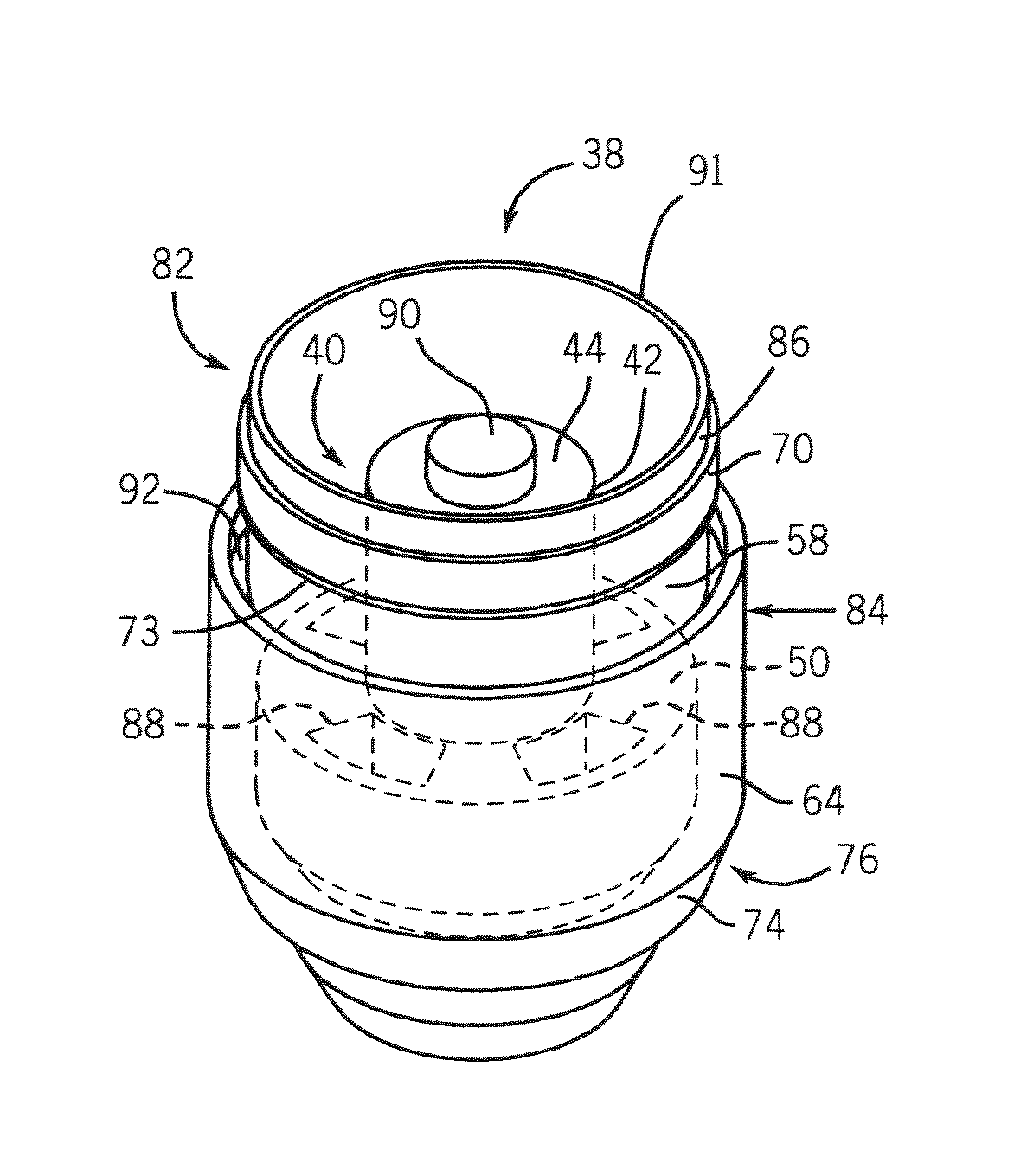
[0021]The present invention is directed to a one-piece consumable assembly. As will be described below, the present invention is directed to a plasma torch consumable. One skilled in the art will readily appreciate that providing a one-piece consumable will be equivalently applicable to other high power output systems such as welding systems and induction heating systems.

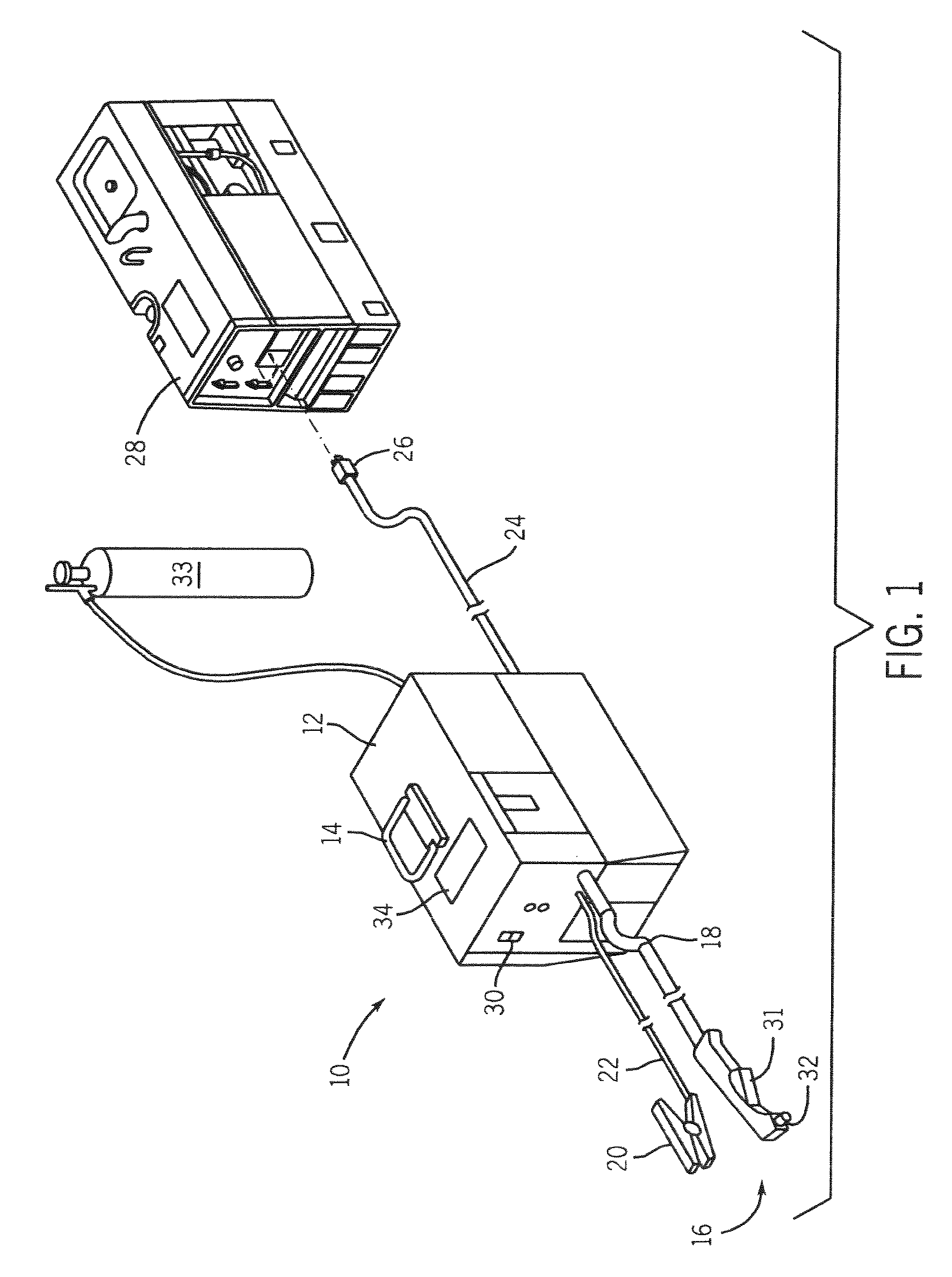
[0022]Referring to FIG. 1, a plasma cutting system 10 is shown. The plasma cutting system is a high voltage system with open circuit output voltages ranging from approximately 230 Volts Direct Current (VDC) to over 300 VDC. The plasma cutting system 10 includes a power source 12 to condition raw power and regulate / control the cutting process. Specifically, the power source 12 includes a processor that, as will be described, receives operational feedback and controls the plasma cutting system 10 accordingly. Power source 12 includes a lifting means 14, such as a handle, which effectuates transportation from one site ...


PUM

PropertyMeasurementUnit
voltagesaaaaaaaaaa
non-conductiveaaaaaaaaaa
poweraaaaaaaaaa

Abstract

An apparatus and method of manufacturing a plasma torch consumable is disclosed. The invention includes at least two of a tip, a shielding cup, an electrode, and a swirl ring being integral to form a unitary one-piece assembly prior to being attached to the torch. Such a construction minimizes the number of parts that must be handled and orientated when connecting the consumable assembly to a plasma torch.

Description

BACKGROUND OF INVENTION[0001]The present invention relates generally to plasma cutting systems and other high power output welding-type systems such as welding and induction heating systems and, more particularly, to a one-piece consumable for use with such systems.[0002]Plasma cutting is a process in which an electric arc is used to cut a workpiece. Plasma cutters typically include a power source, an air supply, and a torch. The torch, or plasma torch, is used to create and maintain the plasma arc that performs the cutting. A plasma cutting power source receives an input voltage from a transmission power line or generator and provides an output voltage to a pair of output terminals, one of which is connected to an electrode and the other of which is connected to the workpiece.[0003]An air supply is used with most plasma cutters to help start the arc, provide the plasma gas to the torch, and cool the torch. A movable or fixed electrode or consumable serves as a cathode and a fixed o...

Claims


Application Information

Patent Timeline
Patent Type & Authority Patents(United States)
IPC IPC(8): B23K10/00B23K10/02H05H1/34
CPCB23K10/00B23K10/02H05H1/34H05H2001/3468H05H2001/3478H05H1/3468H05H1/3478
Inventor MATUS, TIM A.
Owner ILLINOIS TOOL WORKS INC
Why Eureka
Try Eureka