Combustible material plasma high-temperature gasification technique and equipment thereof

A plasma and plasma torch technology, which is applied in the field of plasma high-temperature gasification process and its equipment, can solve the problems of low carbon conversion rate, low proportion of syngas effective components, equipment pollution, etc., and achieve gasification efficiency and carbon conversion rate. Improved, simple fuel pretreatment, low ash content

Active Publication Date: 2010-03-17
SUNSHINE KAIDI NEW ENERGY GROUP CO LTD
View PDF0 Cites 48 Cited by
  • Summary
  • Abstract
  • Description
  • Claims
  • Application Information

AI Technical Summary

Problems solved by technology

However, the test results are not satisfactory, the carbon conversion rate is low, the gasification efficiency is low, and the effective components of the syngas (CO+H 2 ) ratio, low and unstable syngas calorific value, high tar content and other defects are very prominent
[0005] The reason is, on the one hand, that the existing fixed-bed or fluidized-bed gasifiers have poor adaptability to fuels, and one gasifier can only adapt to one kind of fuel, which leads to the stability of its operation. Poor, low carbon conversion
On the other hand, because the composition and calorific value of biomass and municipal solid waste (MSW) are extremely unstable with changes in natural factors such as collection channels, seasons, and climate, the requirements for the control of various parameters in the gasification process are also very high. However, the gasification temperature of existing fixed bed or fluidized bed gasifiers is generally between 800 and

Method used


Image

  • Combustible material plasma high-temperature gasification technique and equipment thereof

Examples


Embodiment Construction

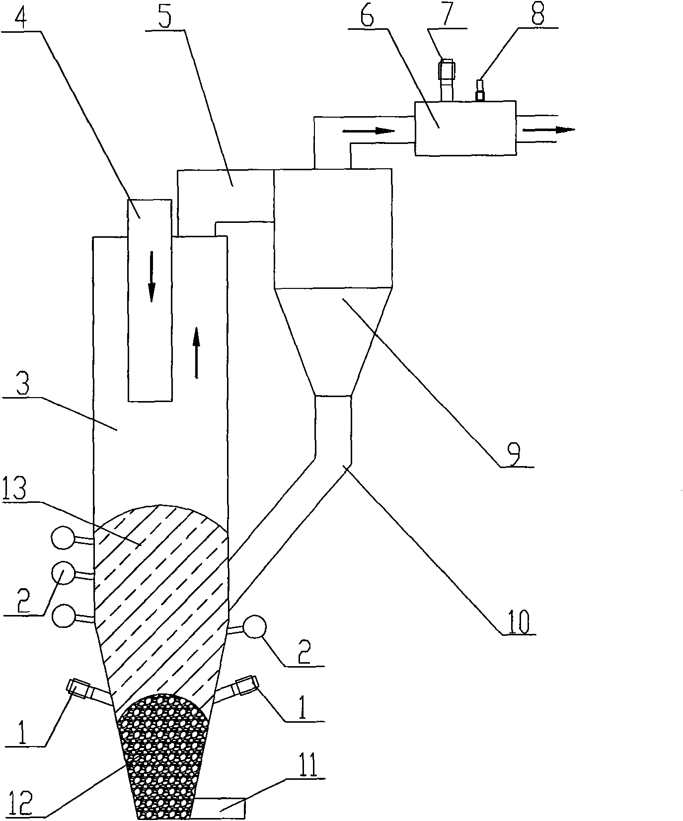
[0038] Below in conjunction with accompanying drawing and specific embodiment, equipment and process of the present invention are described in further detail:

[0039] The combustible material plasma high-temperature gasification equipment shown in the figure is mainly composed of three parts: gasifier, gas-solid separator and tar remover. Wherein, the gasifier has a gasifier shell 3, and the top of the gasifier shell 3 is provided with a feeding device 4, and the length of the feeding device 4 extending into the gasifier can be determined according to the capacity of the actual gasifier. Adjustment. A coke bed 12 can be laid on the bottom of the gasifier shell 3 through the feeding device 4 , and a fuel bed 13 can be laid on the coke bed 12 .

[0040] A primary plasma torch 1 and a primary oxidant nozzle 2 are arranged on the lower side wall of the gasifier shell 3 . In order to ensure a uniform temperature field, there are 2 to 6 primary plasma torches 1, which are evenly ...


PUM


Abstract

The invention relates to a combustible material plasma high-temperature gasification technique and equipment thereof. The technique comprises the following steps: firstly, laying a coke bed layer at the bottom part of a gasification furnace; secondly, putting the combustible material, a fluxing agent and an extra coke on the coke bed layer continuously to form a fuel bed layer; then injecting a primary oxidizing agent, starting a first-stage plasma torch to generate high temperature and high heat, forming a fusing zone at the joint of the coke bed layer and the fuel bed layer, forming a gasifying zone above the fusion zone, gasifying the combustible material to generate crude synthesis gas, and discharging the generated fused slag from the bottom part of the gasification furnace; then introducing the crude synthesis gas into a gas-solid separator for removing impurities to obtain purified synthesis gas; and finally introducing the purified synthesis gas into a detarrer, injecting a secondary oxidizing agent, starting a second-stage plasma torch to generate high temperature and high heat, cracking residual tar therein to obtain fined synthesis gas. The equipment mainly comprises three parts, namely the gasification furnace, the gas-solid separator and the detarrer. The fuel has good adaptability, high gasification efficiency, few tar content in the synthesis gas and high activeingredient.

Description

technical field [0001] The invention relates to a technology for high-temperature gasification treatment of combustible materials, in particular to a combustible material plasma high-temperature gasification process and its equipment. technical background [0002] With the natural growth of the population and the continuous development of the economy, the conventional high-quality fossil fuels as the main source of energy are rapidly decreasing, resulting in long-term and huge energy demand and supply pressure in my country and the world. Facing the general trend of global integration, my country's high energy consumption and low energy efficiency economy will face the severe test of how to survive and develop in the international competition. Regarding the utilization of combustible raw materials such as coal, biomass, and municipal solid waste (MSW), energy conservation and consumption reduction have become one of the most important and effective means to promote the susta...

Claims


Application Information

Patent Timeline
IPC IPC(8): C10J3/18C10J3/08C10J3/20C10J3/84
CPCY02E20/18
Inventor 夏明贵张岩丰林文张亮
Owner SUNSHINE KAIDI NEW ENERGY GROUP CO LTD
Why Eureka
Try Eureka