Nanosturctured Coating and Coating Method

Inactive Publication Date: 2008-04-17
COMMISSARIAT A LENERGIE ATOMIQUE ET AUX ENERGIES ALTERNATIVES
View PDF21 Cites 45 Cited by
  • Summary
  • Abstract
  • Description
  • Claims
  • Application Information

AI Technical Summary

Benefits of technology

[0081]The substrate to be coated is, for obvious reasons, preferably positioned relative to the plasma jet so that the nanoparticles are sprayed directly onto the surface to be coated. Various trials allows the optimum position to be very easily found. The positioning is adjusted for each application, depending on the spraying conditions selected and on the desired microstructure of the coating.
[0082]The high coating growth rate for a method of producing finely structured coatings essentially depends on the percentage of material by weight in the liquid and on the liquid flow rate. It is easily possible with the method of the invention to obtain a nanoparticle coating deposition rate of 1 to 100 μm/min.
[0083]The thin films or coatings that may be obtained by the method of the invention, ranging easily from 0.1 to 50 μm

Problems solved by technology

Hitherto there have not existed techniques that are simple to implement and allow nanoparticle coatings to be obtained that meet the ever increasing requirements of structural and thickness homogeneity, even on the scale of a few microns, and of mechanical strength, owing to the miniaturization of electromechanical and/or optical and/or electrochemical microsystems.
These techniques therefore do not allow coatings consisting of nanoparticles to be formed, nor coatings having thicknesses of less than 100 μm going down to a few microns.
In addition, the coatings obtained have the drawback of being microcracked, especially in the case of depositing ceramics, which brittle materials thus relax the internal stresses.
This therefore clearly limits, right from the outset, the potential applications of plasma spraying.
However, it is not currently possible to make particles with a diameter of less than 1 micron penetrate into a plasma jet using a conventional carrier-gas injector without considerably disturbing the plasma jet.
This results in superconducting ceramics being deposited, but these do not have a nanoscale structure.
In addition, this method is difficult to carry out on an industrial scale as it requires the use of two to four plasma torches operating simultaneously.
However, the coating formed does not have a nanoscale structure.
This technique is limited to radiofrequency plasmas and the resulting deposit

Method used


Image

  • Nanosturctured Coating and Coating Method
  • Nanosturctured Coating and Coating Method
  • Nanosturctured Coating and Coating Method

Examples


example 1

Method of the Invention and Coating Obtained from a Zirconia Sol

[0136]An aqueous 10% zirconia (ZrO2) sol was injected into an argon / hydrogen (75 vol % Ar) transferred (blown)-arc plasma.

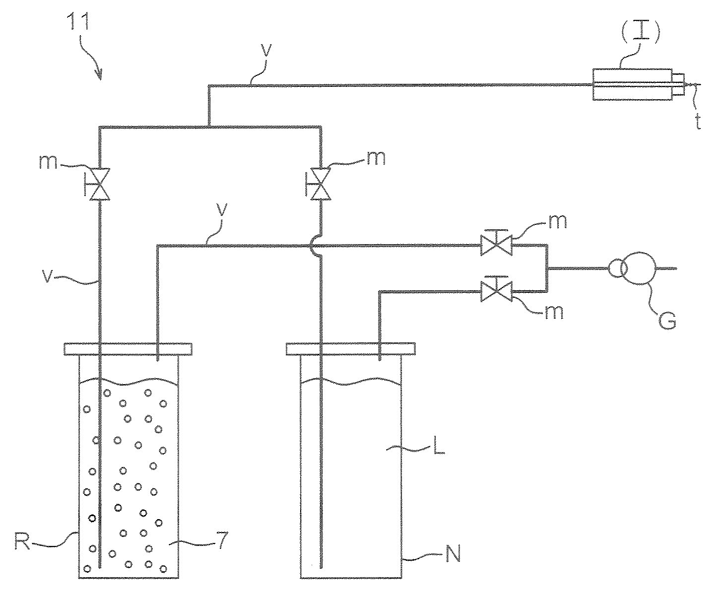
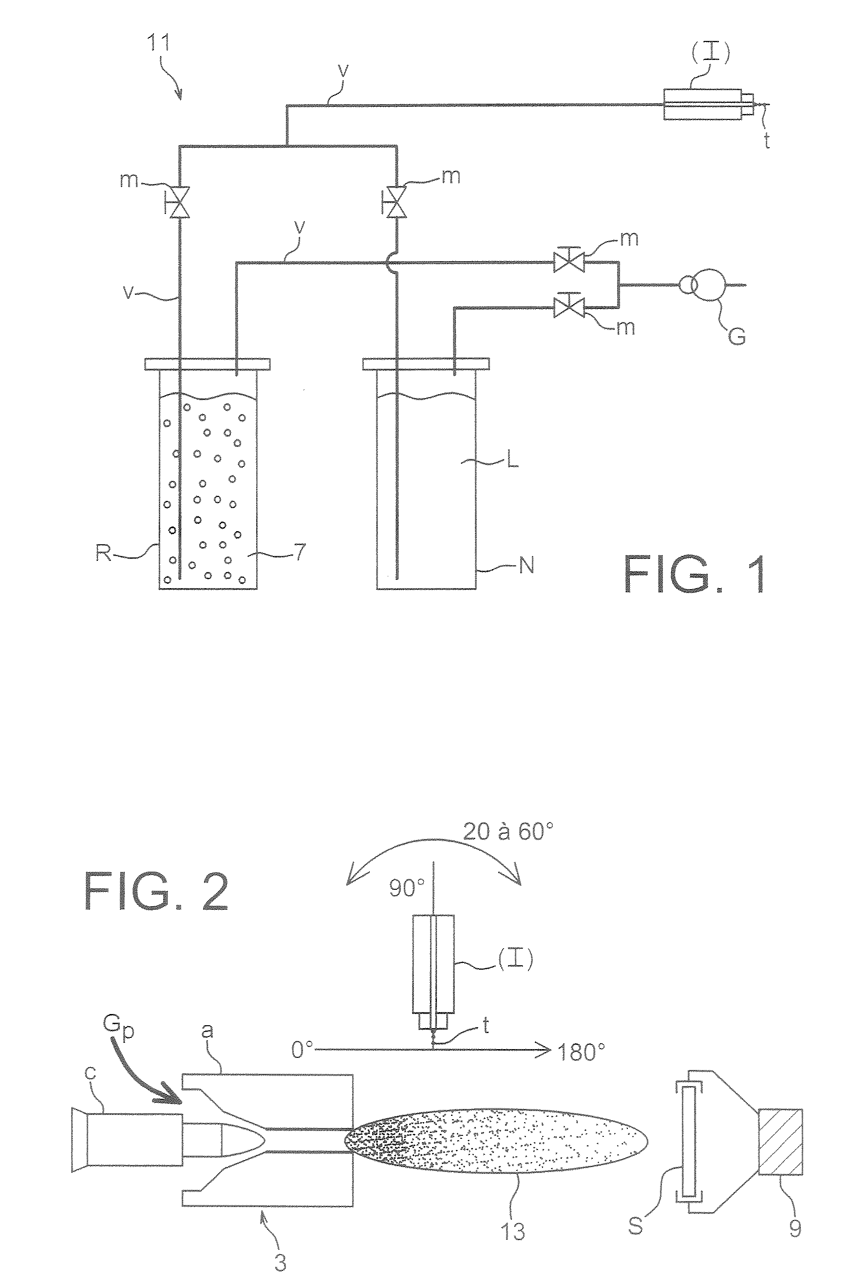
[0137]The experimental set-up used for producing the nanostructured zirconia coatings is shown in FIGS. 1 and 2. It consisted of:[0138]a Sulzer-Metco F4 VB (trade mark) DC plasma torch (3) fitted with an anode of 6 mm inside diameter;[0139]the device for injecting the liquid, described in FIG. 1; and[0140]a device (9) for fixing and for moving the substrate to be coated relative to the torch at a given distance (FIG. 2).

[0141]With regard to the injection device, this comprised a container (R) containing the colloidal sol (7) and a cleaning container (N) containing a cleaning liquid (L) for cleaning the injector and the pipework (v). It also included pipes (v) for conveying the liquids from the containers to the injector (I), pressure-reducing valves (m) for adjusting the pressure in the containers (p...

example 2

[0155]The zirconia sol of Example 1, having specific (dispersion and stabilization) properties of the present invention, was sprayed in a plasma jet as described in Example 1.

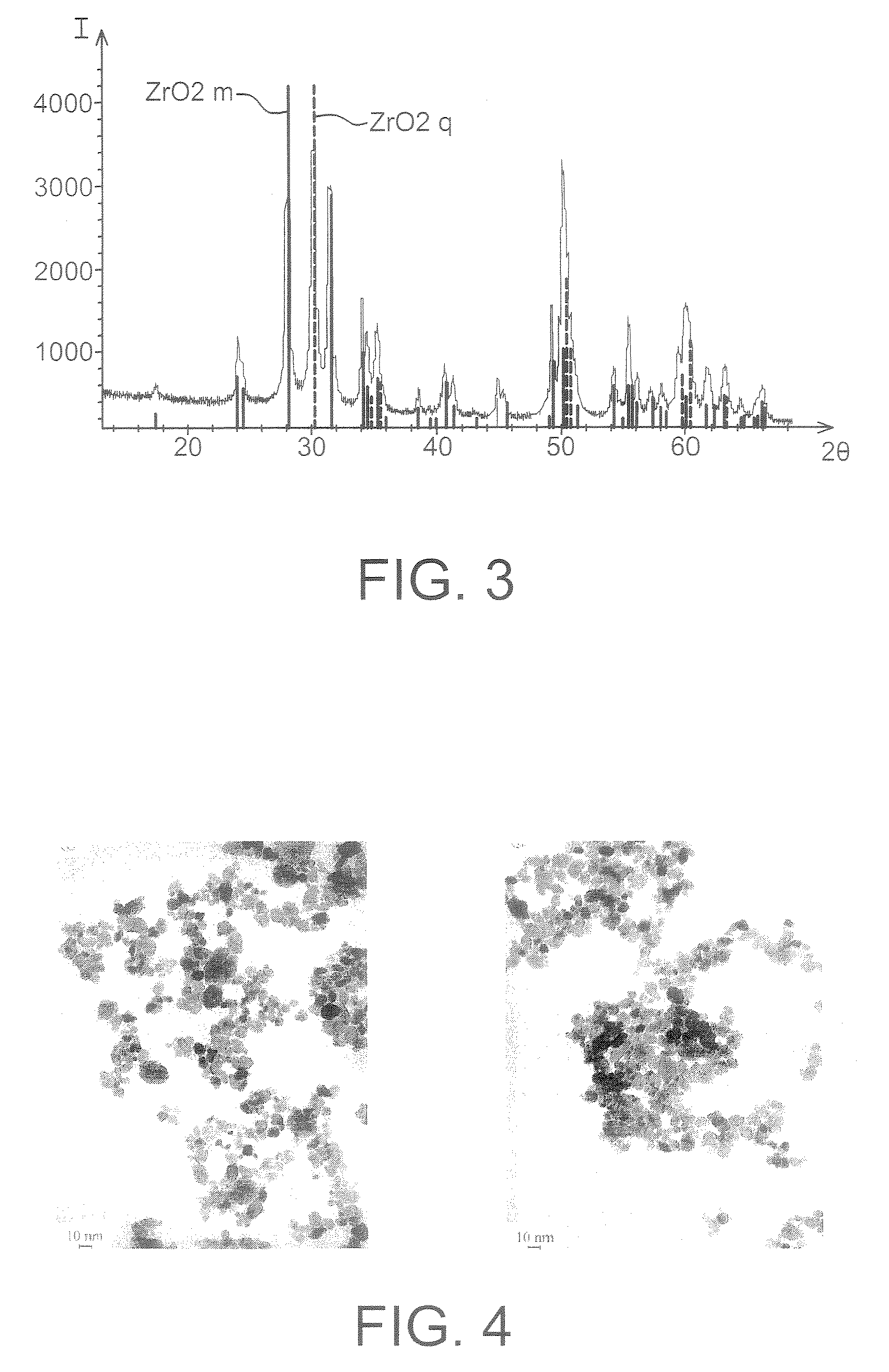
[0156]This zirconia sol consisted of nanoparticles crystallized in monoclinic phase and in tetragonal phase. The size distribution was obtained from TEM micrographs of the zirconia sol. The mean diameter of the zirconia particles was 9 nm. The micrograph on the right in appended FIG. 4 is a TEM micrograph taken on this zirconia sol used. The bar at the bottom left indicates the scale of the micrograph, here representing 10 nm in the micrograph.

[0157]The coating produced by plasma spraying said sol according to the method of the invention consisted, using TEM surface and thickness analysis, of zirconia nanoparticles having a morphology similar to those of the initial sol and with a mean diameter of 10 nm. These measurements can be deduced from the appended FIGS. 6a and 6b. The bar at the bottom right of these mi...

example 3

Preparation of a Nanoparticle Sol

[0162]This example illustrates one of many ways of preparing a nanoparticle sol that can be used for implementing the present invention.

[0163]A colloidal solution of titanium oxide TiO2 was prepared by adding, drop by drop, a titanium tetraisopropoxide solution (0.5 g) dissolved in 7.85 g of isopropanol to 100 ml of a dilute hydrochloric acid solution (pH=1.5) with vigorous stirring. The mixture obtained was kept magnetically stirred for 12 hours.

[0164]Transmission electron microscopy observations showed a mean diameter of the colloids of about 10 nm. The X-ray diagram was characteristic of that of titanium oxide in anatase form.

[0165]The pH of this sol was about 2 and the mass concentration of TiO2 was brought to 10% by distillation (100° C. / 105 Pa).

[0166]Before being used in the method of the invention, the colloidal nanoparticle solution could be filtered, for example to 0.45 μm.


PUM

PropertyMeasurementUnit
Temperatureaaaaaaaaaa
Thicknessaaaaaaaaaa
Angleaaaaaaaaaa

Abstract

The present invention relates to a method of coating a surface with nanoparticles, to a nanostructured coating that can be obtained by this method, and also to a device for implementing the method of the invention. The method is characterized in that it comprises an injection of a colloidal sol of said nanoparticles into a plasma jet that sprays them onto said surface. The device (1) comprises: a plasma torch (3); at least one container (5) containing the colloidal sol (7) of nanoparticles; a device (9) for fixing and for moving the substrate(S); and a device (11) for injecting the colloidal sol into the plasma jet (13) of the plasma torch. The present invention has applications in optical, electronic and energy devices (cells, thermal barriers) comprising a nanostructured coating that can be obtained by the method of the invention.

Description

TECHNICAL FIELD[0001]The present invention relates to a method of coating a surface of a substrate with nanoparticles, to a nanostructured coating that can be obtained by this method, and also to a device for implementing the method of the invention.[0002]The present invention also relates to optical, mechanical, chemical, electronic and energy devices comprising a nanostructured coating that can be obtainable by the method of the invention.[0003]Nanostructured materials are defined as materials organized on a nanoscale, that is to say a scale ranging from a few nm to a few hundred nm. This size range is that corresponding to the characteristic lengths of various physical, electronic, magnetic, optical, superconductivity, mechanical or other processes, and where the surface plays a predominant role in these processes, thereby giving these “nanomaterials” specific and often enhanced properties. Owing to these characteristics, such materials truly have a great potential for the constr...

Claims


Application Information

Patent Timeline
IPC IPC(8): C23C4/04B32B5/16
CPCC23C4/121Y10T428/265Y10T428/26C23C4/123
Inventor VALLE, KARINEBELLEVILLE, PHILIPPEWITTMANN-TENEZE, KARINEBIANCHI, LUCBLEIN, FRANCK
Owner COMMISSARIAT A LENERGIE ATOMIQUE ET AUX ENERGIES ALTERNATIVES
Why Eureka
Try Eureka