Magneto-sensitive integrated circuit

a technology of integrated circuits and magnets, applied in the field of magneto-sensitive integrated circuits, can solve the problems of insufficient a/d conversion precision, inability to achieve sufficient magnetic field detection precision, and inability to fully increase the amplifier's gain, etc., to achieve high precision and increase the gain of the amplifier.

Inactive Publication Date: 2009-01-08
DENSO CORP +1
View PDF11 Cites 48 Cited by
  • Summary
  • Abstract
  • Description
  • Claims
  • Application Information

AI Technical Summary

Benefits of technology

[0013]According to the magneto-sensitive integrated circuit of the invention, since the offset voltage component of the Hall element contained in the amplifier output is removed, the amplifier gain can be increased, and accordingly the magnetic field detection with high precision can be achieved.

Problems solved by technology

That is, the resistance values of four elements making up the bridge are dispersed due to the manufacturing reason, in which its unbalance causes an offset voltage.
However, if the output voltage of the Hall element is amplified by the amplifier, not only the Hall voltage VH but also the offset voltage VOS are amplified, so that the gain of the amplifier can not be fully increased.
As a result, the A / D conversion precision was not ensured, whereby it was difficult to achieve the sufficient magnetic field detection precision.

Method used


Image

  • Magneto-sensitive integrated circuit
  • Magneto-sensitive integrated circuit
  • Magneto-sensitive integrated circuit

Examples


first embodiment

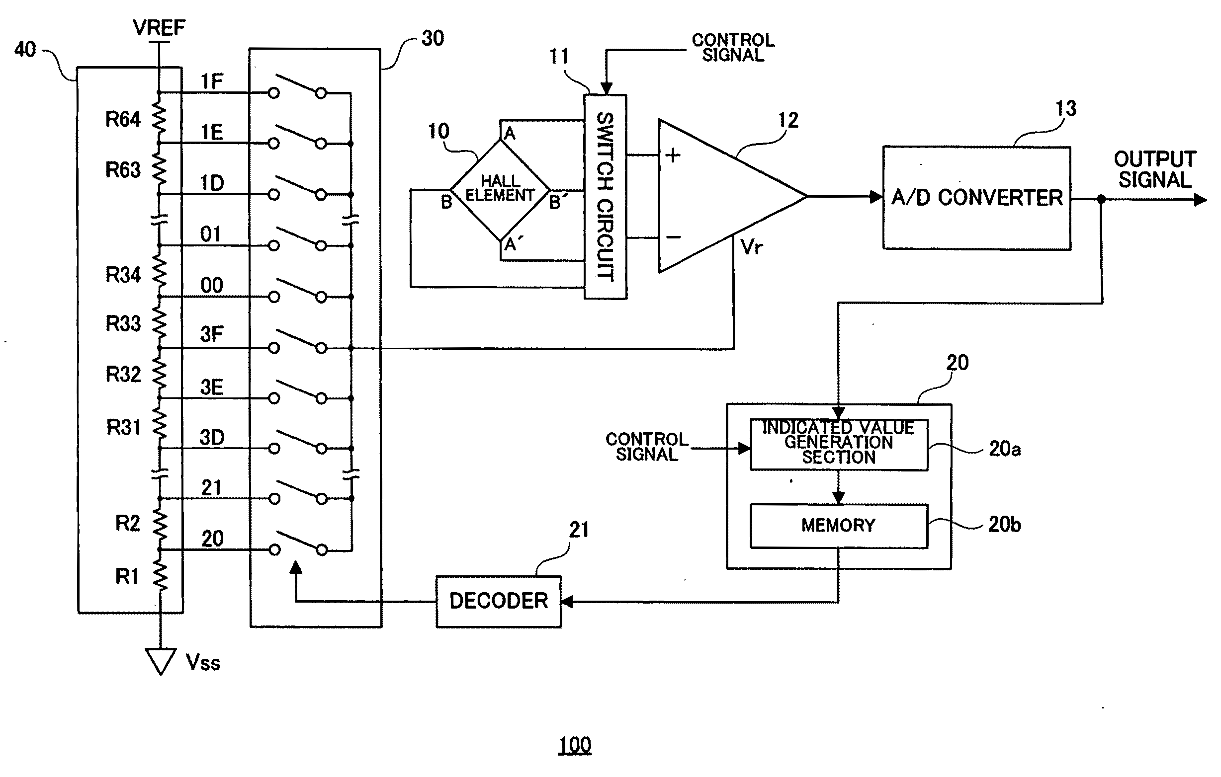
[0029]FIG. 4 shows the configuration of a Hall IC 100 according to a first embodiment of the invention. The Hall IC 100 comprises a Hall element 10, a switch circuit 11, an amplifier 12, an A / D converter 13, a control circuit 20, a decoder 21, a selector 30 and a resistor ladder circuit 40.

[0030]The Hall element 10 is the well-known Hall element formed of a semiconductor thin film made of Si, and having four terminals of A, A′, B and B′.

[0031]The switch circuit 11 switches the connection between the amplifier 12 with a power source (not shown) for feeding electricity to the Hall element 10 and the Hall element 10 in accordance with a control signal supplied from the outside in detecting a magnetic field by a spinning current method. That is, the switch circuit 11, in accordance with the control signal, connects the power source (not shown) between the A-A′ terminals of the Hall element and connects the terminals B and B′ to a non-inverted input terminal and an inverted input termina...

second embodiment

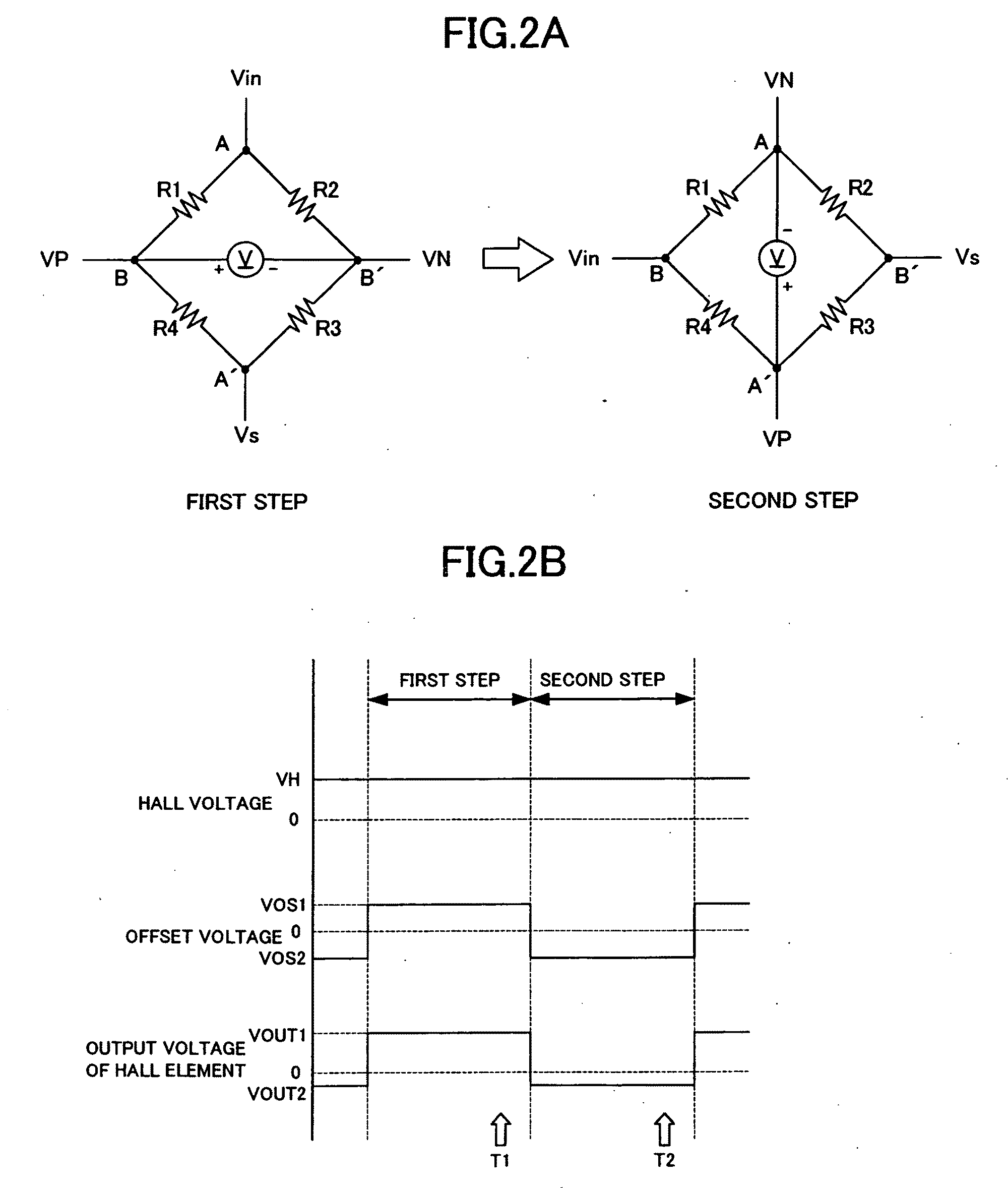
[0051]In the Hall IC 100 of the first embodiment, because the offset voltages occurring at the first and second steps of the spinning current method have equal absolute values and mutually different polarities, to remove them, two reference voltage output terminals generating the voltages shifted by the same value in the positive and negative directions around 0.5*VREF are selected from among the reference voltage output terminals of the resistor ladder circuit 40, and the indicated values (e.g., 3Eh and 00h) corresponding to them are stored in the memory. That is, it is required that two indicated values are stored and read in measuring the magnetic field in the configuration of the first embodiment.

[0052]On the contrary, in a Hall IC 200 of the second embodiment, the magnetic field is measured with only one indicated value to reduce the memory capacity. Herein, if the indicated value is only “3Eh”, for example, it is required to output “00h” based on “3Eh”, in which after making t...

third embodiment

[0065]FIG. 9 is a graph showing the temperature characteristic of the offset voltage when the Hall element is driven at constant current. As shown in FIG. 9, the offset voltage contained in the Hall element output voltage has the temperature characteristic of a quadratic function, in which it is required to correct this to detect the magnetic field at high precision. A Hall IC 300 according to the third embodiment has means for correcting the temperature characteristic of the offset voltage for the Hall element.

[0066]FIG. 10 is a block diagram showing the configuration of the Hall IC 300 according to this embodiment. In the Hall IC 300 according to the third embodiment, the EEPROM 22 is replaced with a control circuit 50, as compared with the configuration of the second embodiment. The control circuit 50 comprises a temperature measurement section 51, a correction value generation section 52, the EEPROMs 53 and 54, and an adder 55.

[0067]The temperature measurement section51 comprise...


PUM


Abstract

A magneto-sensitive integrated circuit which amplifies a magneto-sensitive output voltage of a Hall element by an amplifier to generate an amplified voltage, converts an output voltage of the amplifier into a digital signal by an A/D converter; and generates a reference voltage of magnitude corresponding to an indicated value. The amplifier includes voltage superposition means which superposes a DC voltage corresponding to the reference voltage on the amplified voltage to generate the output voltage of the amplifier.

Description

BACKGROUND OF THE INVENTION[0001]1. Field of the Invention[0002]The present invention relates to a magneto-sensitive integrated circuit such as a Hall IC (integrated circuit) for outputting an electric signal in response to an applied magnetic field.[0003]2. Description of the Related Background Art[0004]If a magnetic field is generated in a direction passing through the principal plane of a Hall element by flowing a current (or applying a voltage) between the input terminals of the Hall element, electrons within the element are bent in the travel direction owing to a Lorenz's force, so that a potential VH occurs between the output terminals. This phenomenon is called a Hall effect, and the potential VH is called a Hall voltage. The Hall voltage VH can be represented by the following expression.VH=K*I*B  (1)[0005]In this way, the Hall element can produce a voltage proportional to a control current I and a magnetic flux density B of the applied magnetic field. Where K is a Hall eleme...

Claims


Application Information

Patent Timeline
Patent Type & Authority Applications(United States)
IPC IPC(8): G01R33/07
CPCG01R33/075G01R33/07
Inventor UTSUNO, KIKUO
Owner DENSO CORP
Why Eureka
Try Eureka