Temperature detection circuit

a technology of temperature detection and circuit, applied in the direction of instruments, heat measurement, calorimeters, etc., can solve the problem of not being able to accurately detect the ambient temperature around the devi

Inactive Publication Date: 2009-01-08
RICOH KK
View PDF29 Cites 13 Cited by
  • Summary
  • Abstract
  • Description
  • Claims
  • Application Information

AI Technical Summary

Benefits of technology

[0014]This patent specification describes a novel temperature detection circuit that includes a first voltage source circuit to generate a first voltage having a temperature dependence by utilizing a work function difference of gate electrodes of a plurality of field effect transistors, a second voltage source circuit to generate a reference voltage having no temperature dependence by utilizing a work function difference of gate electrodes of a plurality of field effect transistors, a correction circuit configured to correct the reference voltage and output a corrected voltage, and a subtraction amplifier configured to subtract the corrected voltage from the first voltage, amplify a resulting subtracted voltage, and output a resulting amplified voltage as a correction voltage signal to adjust a temperature coefficient of the correction voltage signal.
[0015]This patent specification further describes a novel temperature detection circuit which includes a first voltage source circuit to generate a first voltage having a temperature dependence by utilizing a work function difference of gate electrodes of a plurality of field effect transistors, a second voltage source circuit to generate a reference voltage having no temperature dependence by utilizing a work function difference of gate electrodes of a plurality of field effect transistors, a subtraction amplifier configured to subtract the corrected voltage from the first voltage, amplify a resulting subtracted voltage, and output a resulting amplified voltage so as to correct a temperature coefficient in an output voltage output from the subtraction amplifier, an A / D conversion circuit configured to convert the output voltage of the subtraction amplifier and output a converted digital signal, and a correction circuit configured to correct the converted digital signal and output a corrected digital signal.

Problems solved by technology

Accordingly, it may not be possible to accurately detect an ambient temperature around the device under low voltage conditions with known temperature detection circuits.

Method used


Image

  • Temperature detection circuit
  • Temperature detection circuit
  • Temperature detection circuit

Examples


first example embodiment

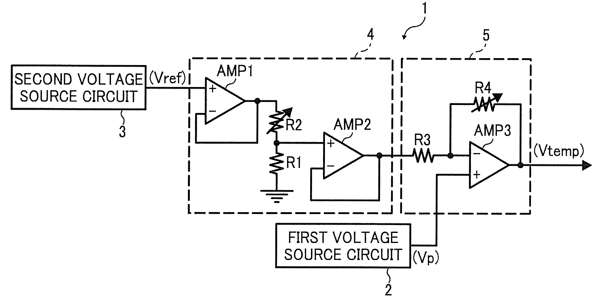
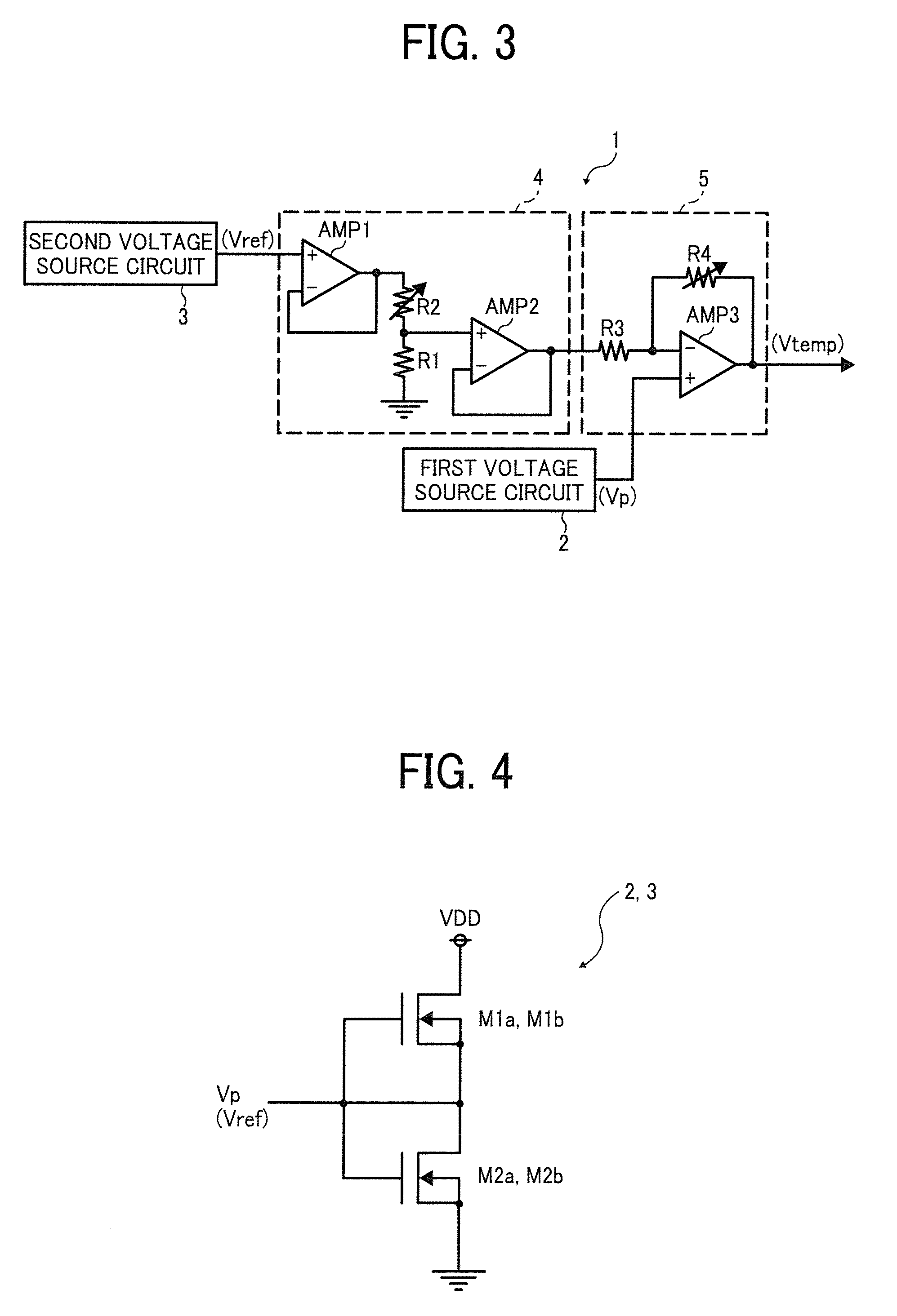
[0030]FIG. 3 is an example circuit of a temperature detection circuit according to a first example embodiment. In FIG. 3, the temperature detection circuit 1 includes a first and second voltage sources 2 and 3, a correction circuit 4, and an subtraction amplifier circuit 5. The first voltage source circuit 2 generates a positive PTAT voltage Vp having a negative temperature dependence by utilizing a work function difference of gate electrodes of two field effect transistors.

[0031]The second voltage source circuit 3 generates a reference voltage Vref having no temperature dependence using a work function difference of gate electrodes of two field effect transistors. The correction circuit 4 corrects the reference voltage Vref output from the second voltage source circuit 3, and outputs a corrected reference voltage Vref. The subtraction amplifier circuit 5 subtracts the reference voltage Vref output from second voltage source circuit 3 from the PTAT voltage Vp output from the first v...

second example embodiment

[0059]In the temperature detection circuit according to the first example embodiment, the temperature detection circuit outputs an analog signal. In a second example embodiment, a temperature detection circuit outputs a digital signal.

[0060]FIG. 7 is a circuit diagram of the temperature detection circuit according to the second example embodiment. In FIG. 7, identical reference characters are assigned to identical or similar circuit members shown in FIG. 3 and descriptions thereof are omitted.

[0061]The temperature detection circuit 10 outputs a digital signal which is in directly proportional to temperature T as a line shown in FIG. 8, and a coefficient of the line is determined to be “16”. A digital value of “0” is output at 0° C., therefore, the temperature detection circuit 10 has a resolution of 0.0625° C.

[0062]The temperature detection circuit 10 includes a first and second voltage source circuits 2 and 3, an subtraction amplifier circuit 5, a switch 12, a double integration A / ...


PUM

PropertyMeasurementUnit
temperatureaaaaaaaaaa
work functionaaaaaaaaaa
reference voltageaaaaaaaaaa

Abstract

A temperature detection circuit includes a first voltage source circuit to generate a first voltage having a temperature dependence by utilizing a work function difference of gate electrodes of a plurality of field effect transistors, a second voltage source circuit to generate a reference voltage having no temperature dependence by utilizing a work function difference of gate electrodes of a plurality of field effect transistors, a correction circuit configured to correct the reference voltage and output a corrected voltage, and a subtraction amplifier configured to subtract the corrected voltage from the first voltage, amplify a resulting subtracted voltage, and output a resulting amplified voltage as a correction voltage signal to adjust a temperature coefficient of the correction voltage signal.

Description

CROSS-REFERENCE TO RELATED APPLICATION[0001]This patent specification is based on and claims priority from Japanese Patent Application No. 2007-174019 filed on Jul. 2, 2007 in the Japan Patent Office, the entire contents of which are hereby incorporated by reference herein.BACKGROUND[0002]1. Field of the Invention[0003]The present invention relates to a temperature detection circuit, and more specifically, to a temperature detection circuit capable of high-accuracy temperature detection under low power voltage conditions.[0004]2. Description of the Related Art[0005]Recently, there is increasing demand for portable devices, such as mobile phones, that are capable of low voltage operation with low power consumption. For such devices, it is extremely important to have a high-accuracy temperature detection circuit capable of operating under such low power voltage conditions.[0006]FIG. 1 is a circuit diagram of a known temperature detection circuit. The temperature detection circuit incl...

Claims


Application Information

Patent Timeline
Patent Type & Authority Applications(United States)
IPC IPC(8): G01K15/00
CPCG01K15/00G01K7/01
Inventor NAGAHISA, TAKESHI
Owner RICOH KK
Why Eureka
Try Eureka