Damper for turbomachine vanes

a technology for turbomachine vanes and dampers, which is applied to non-positive displacement fluid engines, dampers with inertia effect, liquid fuel engine components, etc., and can solve problems such as wear and tear

Active Publication Date: 2009-01-08
SN DETUDE & DE CONSTR DE MOTEURS DAVIATION S N E C M A
View PDF9 Cites 28 Cited by
  • Summary
  • Abstract
  • Description
  • Claims
  • Application Information

AI Technical Summary

Benefits of technology

[0017]Another feature is that the mass of the damper is adjusted in such a way as to be interchangeable without requiring rebalancing of the rotor on which it is mounted. The mass is adjusted by simply removing material from the region of the center of gravity of the weight.
[0018]If necessary, the mass of the damper can be further adjusted by using a second weight continuing on from said weight on the spring side.

Problems solved by technology

On the other hand, problems of wear can occur due to rubbing of the parts against each other.

Method used


Image

  • Damper for turbomachine vanes
  • Damper for turbomachine vanes
  • Damper for turbomachine vanes

Examples


Embodiment Construction

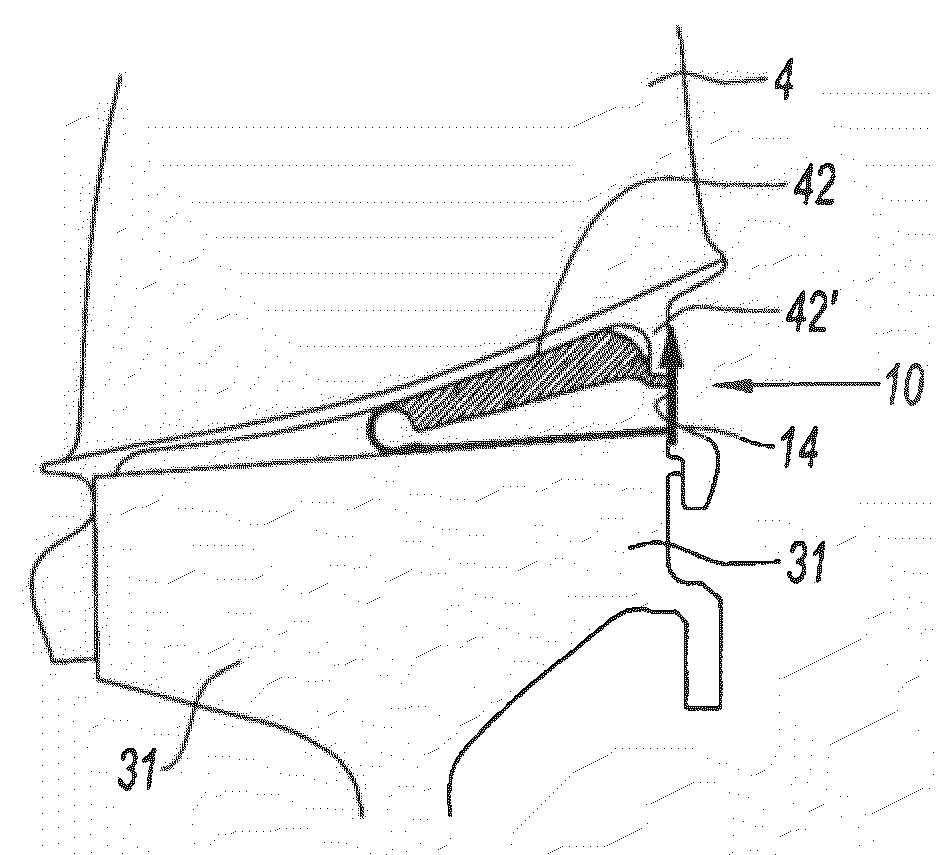
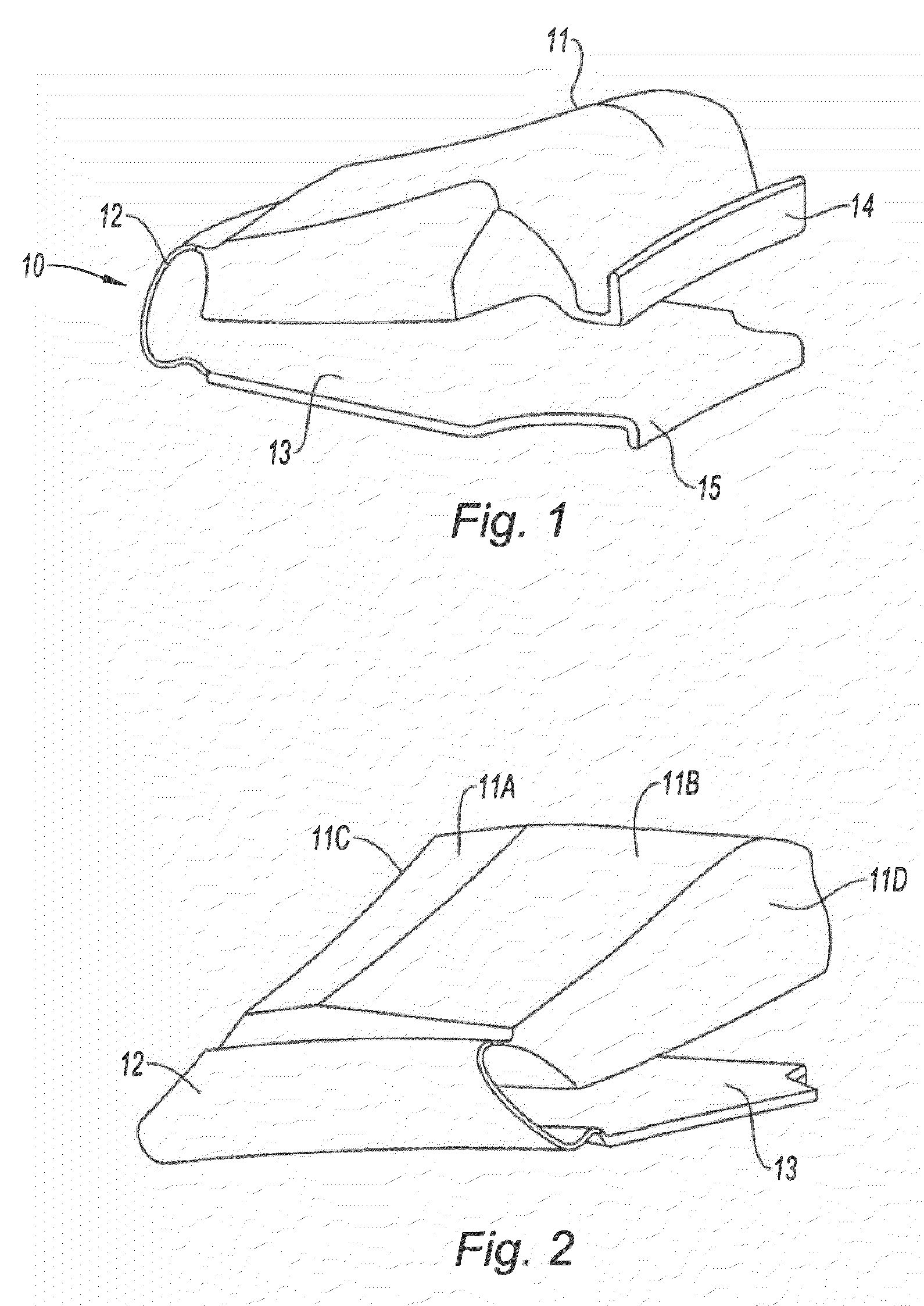
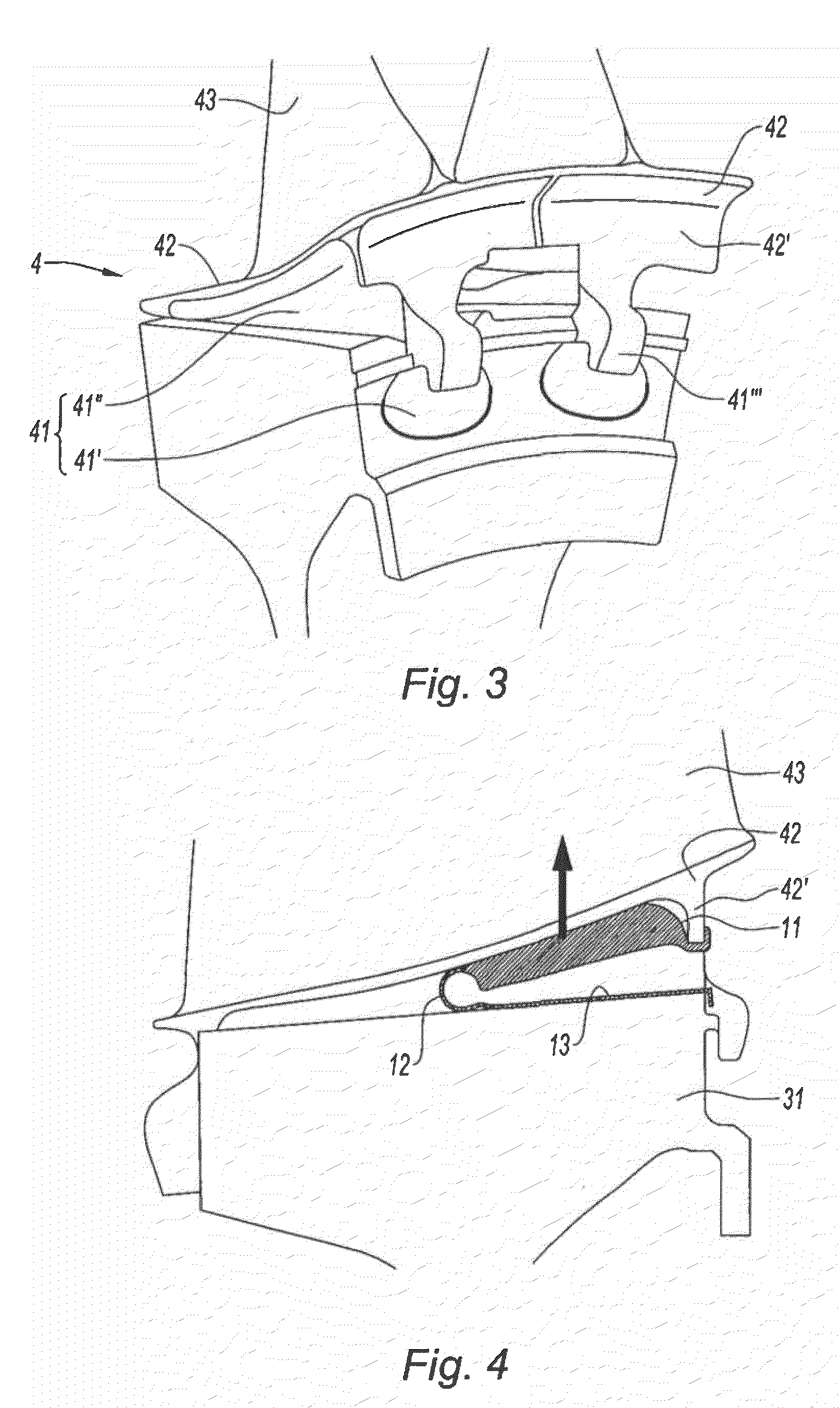
[0030]FIGS. 1 and 2 are perspective views of a damper 1 according to the invention. It comprises a weight 11, a spring 12 and a bearing plate 13. The weight is of a shape suited to the environment in which the damper is intended to be installed. In this example the weight is of an elongate shape for fitting into the unoccupied space between two adjacent vanes of a compressor of a gas turbine engine, underneath the platforms of the two vanes. The weight has two surfaces 11A and 11B for contact with the platforms, and two lateral surfaces 11C and 11D. The weight 11 is continued at one end by a spring 12 in the form of a leaf curved around an axis perpendicular to the longitudinal direction of the weight. The spring leaf 12 is connected to a flat bearing plate in the form of a leaf. In the example illustrated, the weight forms an angle with the plane of the bearing plate when the spring is at rest and unstressed. The ends of both the weight and the bearing plate furthest from the sprin...


PUM


Abstract

The present invention relates to a turbomachine vane damper constructed so as to be housed between the lower face of the platforms of two adjacent turbomachine vanes and the rim of the rotor disk on which the vanes are mounted. This damper is noteworthy in that it comprises a weight (11), a bearing plate (13) and a spring (12), the spring connecting the weight to the bearing plate.

Description

[0001]The present invention relates to turbomachines comprising at least one rotor disk provided with vanes on the rim, and concerns a dynamic damper mounted underneath the vane platform. It is more particularly concerned with axial compressors.BACKGROUND OF THE INVENTION[0002]A turbomachine for which the invention is intended is an axial compressor or an axial turbine of the type comprising at least one rotor disk with housings recessed into its rim for vanes which extend radially relative to the axis of the machine. The vanes themselves comprise a root, an airfoil and, between the two, a platform. The root is inserted into the housing of the disk, the airfoil is swept by the flow of propellant gases and the platform forms a portion of the radially inside surface of the gas stream.[0003]The purpose of dynamic damping is to modify the dynamic behavior of the vanes of the turbomachine by adding a mass underneath the platforms of the vanes. The loads thus generated in operation reduce...

Claims


Application Information

Patent Timeline
Patent Type & Authority Applications(United States)
IPC IPC(8): F01D25/04F01D5/22F16F7/104
CPCF01D5/22F01D5/26F01D5/3007Y10S416/50F05D2250/314F05D2300/601F05D2300/603Y02T50/672F05D2220/36F05D2260/38F01D5/323F01D5/3092
Inventor CAUCHETEUX, MATHIEUDURDEVIC, GORANLEFEBVRE, ERIC
Owner SN DETUDE & DE CONSTR DE MOTEURS DAVIATION S N E C M A
Why Eureka
Try Eureka