Production method of plugged honeycomb structure

Inactive Publication Date: 2009-01-08
NGK INSULATORS LTD
View PDF1 Cites 15 Cited by
  • Summary
  • Abstract
  • Description
  • Claims
  • Application Information

AI Technical Summary

Benefits of technology

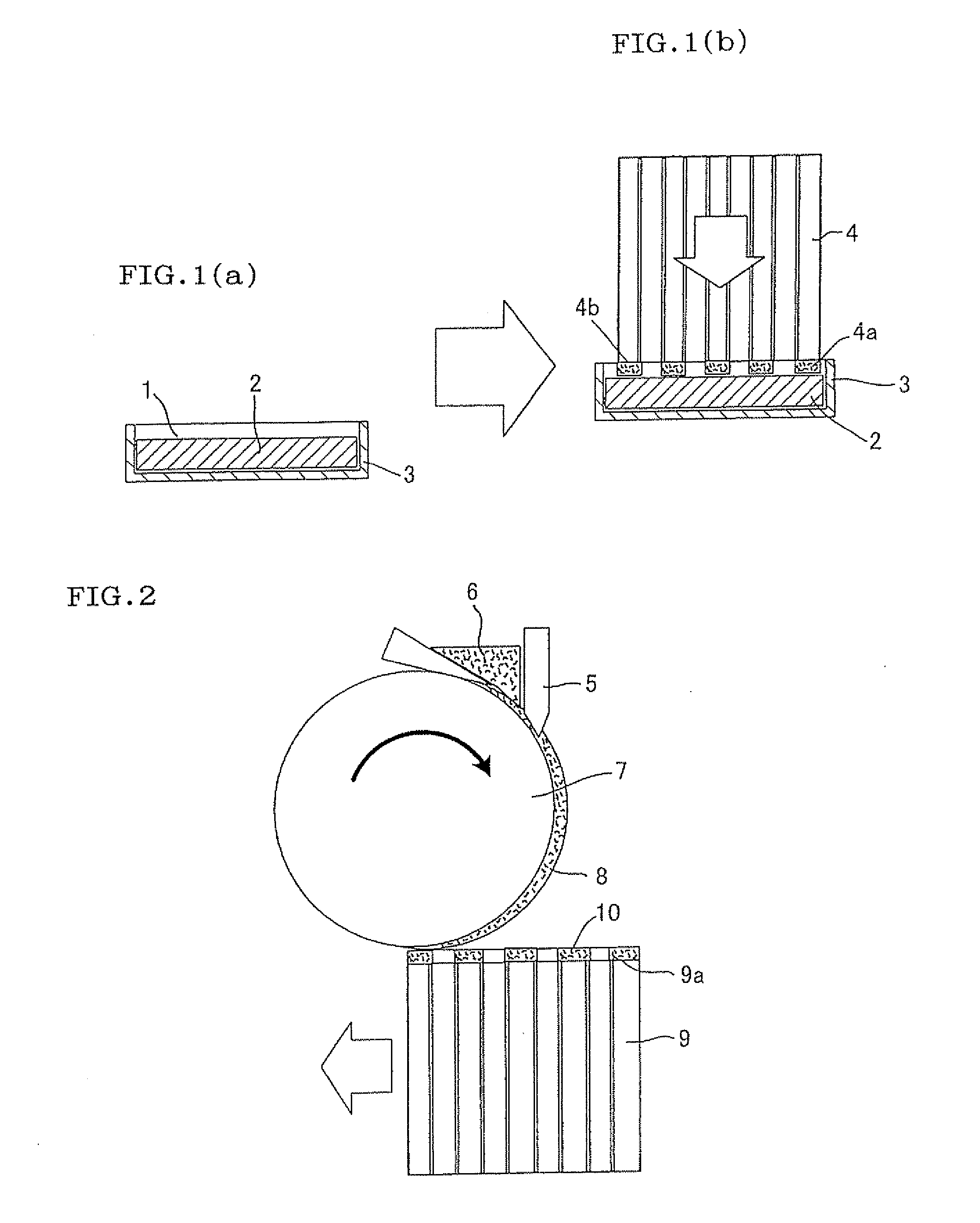
[0017]According to the manufacturing method of the present invention, the following effect is produced. That is, in the method of manufacturing the plugged honeycomb structure in which the plugging portion is formed in one opening end portion of each of predetermined cells of the cylindrical honeycomb structure including the plurality of cells divided by the porous partition walls to form the channels of the fluid in the form of the honeycomb, a plugging depth is easily made uniform by a step of holding the slurry-like plugging material by the flexible porous member. A problem to be solved by the present invention is achieved. Furthermore, the plugging depth can freely be adjusted in accordance with a compressive deform

Problems solved by technology

Therefore, there is an unsolved problem that the plugging depth of the slurry-like plugging material at the outer peripheral portion of the honeycomb structure easily decreases.
In addition, th

Method used


Image

  • Production method of plugged honeycomb structure
  • Production method of plugged honeycomb structure
  • Production method of plugged honeycomb structure

Examples


Example

Example 1

[0055]For example, as a raw material, a cordierite forming material including talc, kaolin and alumina described above as main materials is blended with water and a binder, dispersed, mixed and kneaded to obtain a forming material. The material is extruded into a columnar shape by a clay kneader, and extruded by an extruder to obtain a formed honeycomb body. When a honeycomb structure is manufactured using the formed body obtained in this manner, the resultant formed body is dried and cut into a predetermined length to obtain a dried body, and cell groups at opposite end surfaces of this dried body are alternately plugged and then fired to obtain a fired body. Next, partition walls of about one to three cells are ground and removed from an outer peripheral wall and an outermost periphery of the resultant fired body. Subsequently, an outer periphery is coated with a ceramic coating material to form the outer peripheral wall. In consequence, the honeycomb structure of cordier...

Example

Example 2

[0058]As shown in FIG. 5, plugging was performed to a honeycomb structure similar to that of Example 1 in three ways by a method where a plurality of planar flexible porous members 32 are disposed in series and moved on a conveyer 35 to plug in multistage. For convenience, the honeycomb structure is shown by a cross-sectional view. The first plugging could give a plugging depth of about 3 mm by disposing a plurality of porous members (thickness of about 0.5 mm) 32 in series in a vessel 33 containing a slurry-like plugging material 31 and performing plugging 6 times. The IC second plugging could give a plugging depth of about 1.5 mm by disposing a plurality of porous members (thickness of about 0.2 mm) 32 in series in a vessel 33 containing a slurry-like plugging material 31 and performing plugging 6 times. The third plugging could give a plugging depth of about 1 mm by disposing a plurality of porous members (thickness of about 0.15 mm) 32 in series in a vessel 33 containin...

Example

Example 3

[0059]By a method where a flexible porous member 52 was formed on a surface of a roller 57 and rotated for plugging as shown in FIG. 7, plugging was performed in three ways to a honeycomb structure similar to that of Example 1. The first plugging could give a plugging depth of about 3 mm by pressing and rotating the roller 57 having a porous member (thickness of about 0.5 mm) 52 impregnated with a slurry-like plugging material and formed on the surface thereof against the upper end face of the honeycomb structure 54 and performing plugging 6 times. The second plugging could give a plugging depth of about 1.5 mm by pressing and rotating the roller 57 having a porous member (thickness of about 0.2 mm) 52 impregnated with a slurry-like plugging material and formed on the surface thereof against the upper end face of the honeycomb structure 54 and performing plugging 6 times. The third plugging could give a plugging depth of about 1 mm by pressing and rotating the roller 57 hav...


PUM

PropertyMeasurementUnit
Flexibilityaaaaaaaaaa
Depthaaaaaaaaaa

Abstract

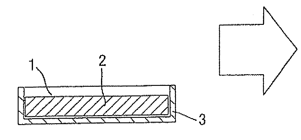
There is disclosed a plugged honeycomb structure manufacturing method capable of easily manufacturing a plugged honeycomb structure for use in a filter or the like at low costs so that deposits disposed on an end surface of the structure are reduced, a uniform plugging depth is achieved and especially the plugging depth of a slurry-like plugging material at an outer peripheral portion of the honeycomb structure is easily made uniform. In the method of manufacturing the plugged honeycomb structure in which the plugging portion is formed in one opening end portion of each of predetermined cells of a cylindrical honeycomb structure including a plurality of cells divided by porous partition walls to form channels of a fluid in the form of a honeycomb, a flexible porous member 2 impregnated beforehand with a slurry-like plugging material 1 is pressed onto an end surface 4a of a honeycomb structure 4 to thereby fill cell passages of the honeycomb structure 4 with the slurry-like plugging material 1 contained in the flexible porous member 2 and form plugging portions 4b.

Description

TECHNICAL FIELD[0001]The present invention relates to a method of manufacturing a plugged honeycomb structure. The present invention more particularly relates to a plugged honeycomb structure manufacturing method capable of easily manufacturing a plugged honeycomb structure at low costs so that deposits deposited on an end surface of the structure are reduced in a case where the structure is used as a filter or the like. The present invention more particularly relates to a method of manufacturing a plugged honeycomb structure in which a plugging depth of a honeycomb structure can easily be made uniform.BACKGROUND ART[0002]In recent years, in various fields including cars, chemistry, powers, irons and steels and industrial waste disposal, a plugged honeycomb structure made of a ceramic having excellent resistances to heat and corrosion has been used as a dust collecting filter for use in applications such as environmental countermeasures for prevention of pollution and product recove...

Claims


Application Information

Patent Timeline
IPC IPC(8): B32B3/12B29C47/06
CPCB01D46/0001B01D46/2418Y10T428/24157B28B11/007B28B11/006
Inventor ICHIKAWA, YUKIHITO
Owner NGK INSULATORS LTD
Why Eureka
Try Eureka