Process for producing honeycomb structure

a honeycomb structure and honeycomb technology, applied in chemical/physical processes, domestic applications, machines/engines, etc., can solve the problems of difficult production of honeycomb structures of high porosity, high clay kneading, and high cost, and achieve high porosity, high porosity, and high porosity.

Active Publication Date: 2009-01-08
NGK INSULATORS LTD
View PDF9 Cites 23 Cited by
  • Summary
  • Abstract
  • Description
  • Claims
  • Application Information

AI Technical Summary

Benefits of technology

[0018]According to the present invention there can be provided a process for producing a honeycomb structure having a high porosity and a sharp pore diameter distribution which is useful as a filter for exhaust gas, particularly a diesel particulate filter (DPF) for trapping the particulate, etc., present in the exhaust gas of diesel engine.
[0019]It is noteworthy that, in a process for producing a honeycomb structure of the present invention, as the clay used for forming of the honeycomb structure of the present invention, there is used a cordierite-forming raw material which has a controlled particle size distribution with each of the components constituting the cordierite-forming raw material having as well a controlled particle size distribution, whereby the closest packing of the cordierite-forming raw material can be avoided, and pores are formed in the honeycomb structure based on the packed condition of each component. As a result, a honeycomb structure of high porosity can be obtained, for example, even by using no pore former in the clay. In addition, since no pore former is used, sharpening of a pore diameter distribution of the honeycomb structure can be realized with maintaining high porosity.

Problems solved by technology

However, such continuous production by a continuous forming machine brings about higher kneading of clay.
This induces easy collapse of the pore former contained in the clay and makes difficult the production of a honeycomb structure of high porosity, or, in view of the collapse of the pore former, it is necessary to use a large amount of a pore former, which is relatively expensive, in the clay to be formed.
These have been problems.
In addition, due to variance in particle size distribution of the pore former and collapse generation upon production, it has been difficult to stably mass-produce a honeycomb structure having a sharp pore diameter distribution.

Method used


Image

  • Process for producing honeycomb structure
  • Process for producing honeycomb structure
  • Process for producing honeycomb structure

Examples


example 1

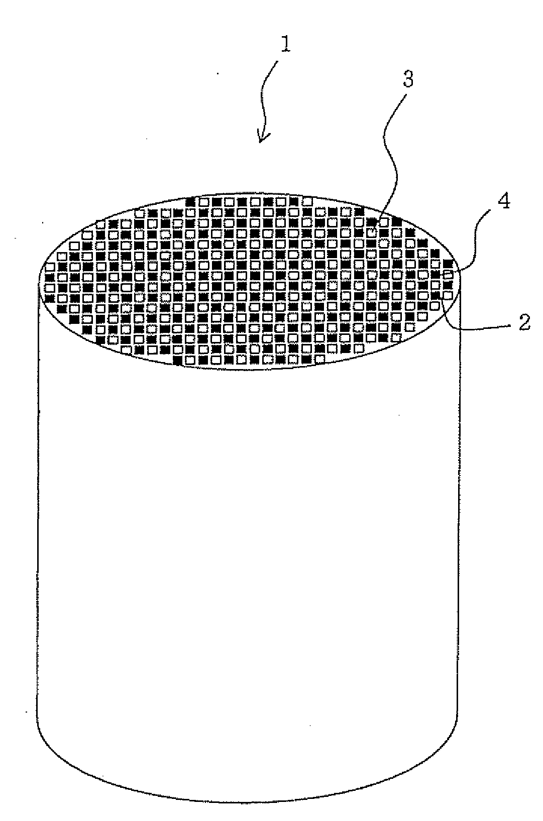
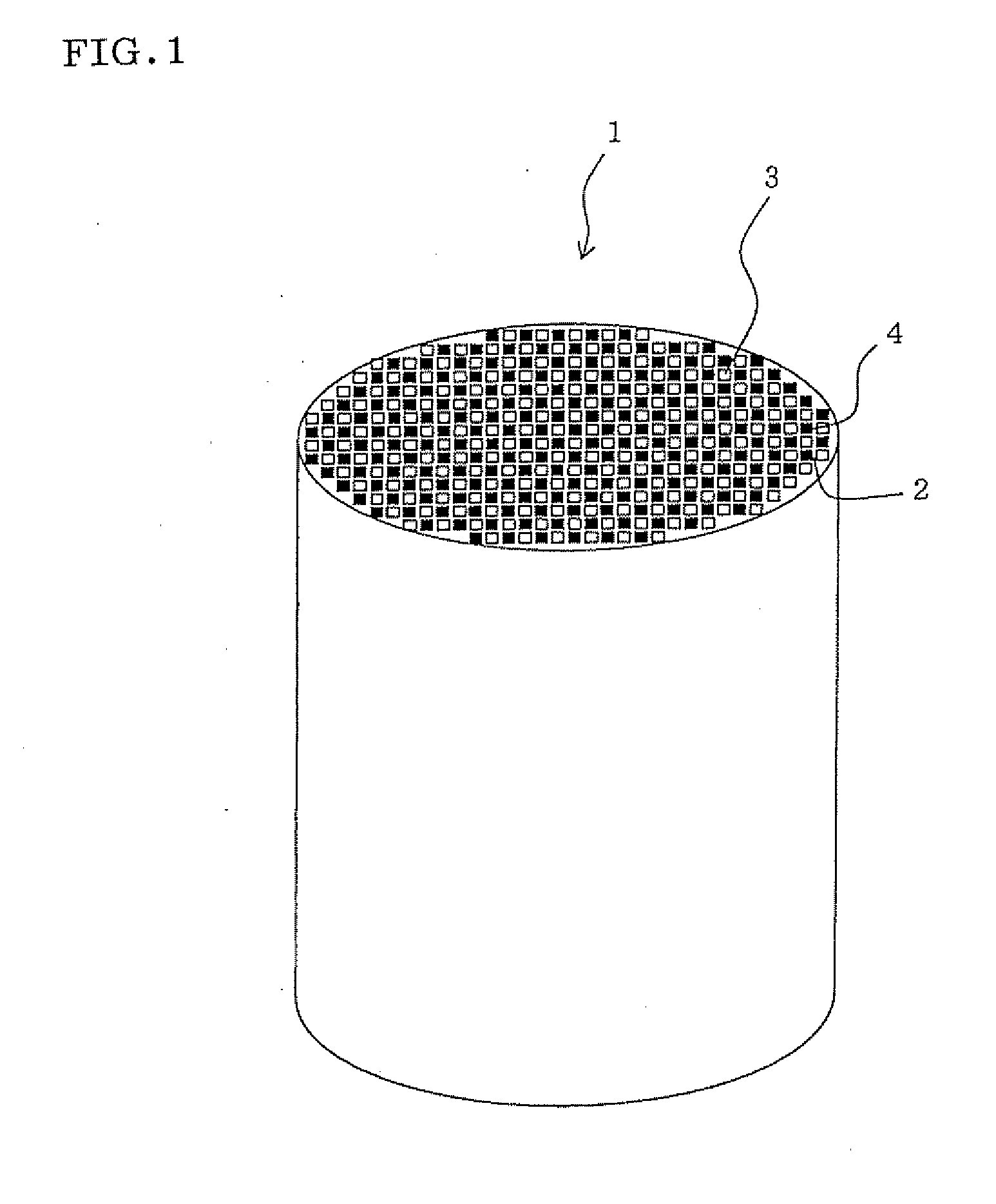
[0080]There was produced a cordierite-based honeycomb structure (a honeycomb filter) having plugging portions each formed alternately at one opening of each cell so that they look checkerwise at each end of the honeycomb structure. As a specific production process, as shown in Table 1, 44 volume parts of talc A, 22 volume parts of kaolin A, 19 volume parts of alumina A, and 15 volume parts of silica A were mixed to prepare a cordierite-forming raw material. In Table 1 is shown the compounding ratio of the cordierite-forming raw material prepared. In Table 2 are shown the 10 volume % particle size (V10) [μm], 50 volume % particle size (V50) [μm] and 90 volume % particle size (V90) [μm] in the volume particle size distribution and the volume particle size distribution ratio (V90 / V10) of each of the raw materials used in Examples.

TABLE 1Name ofExamplesComparative ExamplesComponent1234567891234567Cordierite-Talc A444447——44474448———10212723formingTalc B———44————————————rawTalc C————44——...

examples 2 to 9

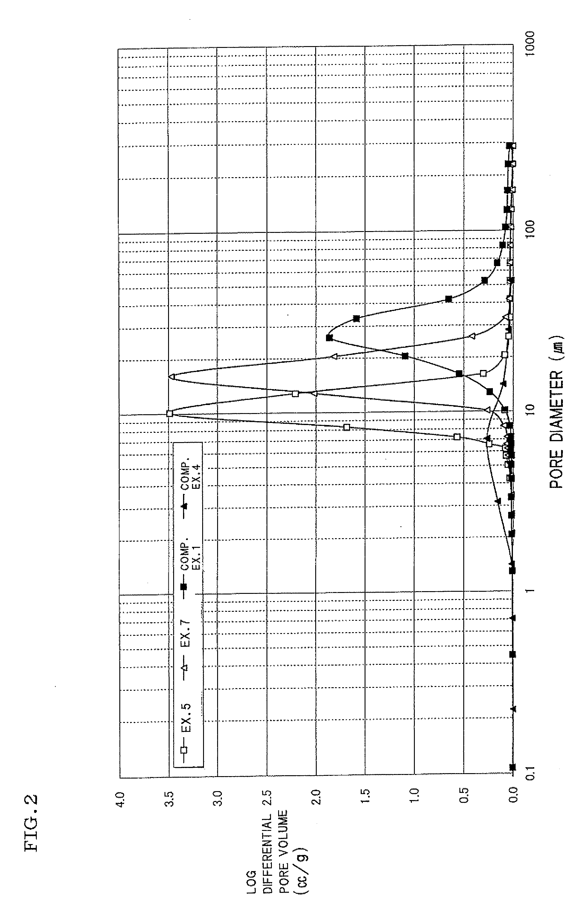
[0088]Honeycomb structures were produced in the same manner as in Example 1 except that the compounding ratio of each of the components constituting the cordierite-forming raw material was changed as shown in Tables 1 and 2. Each honeycomb structure obtained was measured for porosity (%). The results of measurement are shown in Table 3.


PUM

PropertyMeasurementUnit
particle sizeaaaaaaaaaa

Abstract

A process for producing a honeycomb structure by obtaining clay from a cordierite-forming raw material containing an alumina source, a silica source, and a magnesia source; and forming the clay into a honeycomb shape, wherein a material having, in its volume particle size distribution, a 50 volume % particle size (V50) [μm] of 1 to 25 μm is used, as each of alumina source, silica source, and magnesia source; and a material having, in the volume particle size distribution of the whole cordierite-forming raw material, a ratio of 90 volume % particle size (Vall90) [μm] to 10 volume % particle size (Vall10) [μm] [a volume particle size distribution ratio (Vall90/Vall10)] of 10 or less and a difference (Vall90−Vall10) between 90 volume % particle size (Vall90) [μm] and 10 volume % particle size (Vall10) [μm] of 25 μm or less is used, as the cordierite-forming raw material.

Description

TECHNICAL FIELD[0001]The present invention relates to a process for producing a honeycomb structure. More particularly, the present invention relates to a process for producing a honeycomb structure of high porosity which is useful as a filter for exhaust gas, particularly a diesel particulate filter (DPF) for trapping the particulate matter, etc., present in the exhaust gas of diesel engine.[0002]A requirement for removal of particulate matter and harmful substances present in the exhaust gases of internal combustion engine, boiler, etc., is growing in view of their influence on environment. The regulation with respect to, in particular, the removal of the particulate matter (hereinafter may be referred to as “PM”) discharged from diesel engine is being intensified worldwide; and it is drawing attention to use, as a filter for removing the PM (a diesel particulate filter, this may hereinafter be referred to as “DPF”), a filter made of a honeycomb structure (a honeycomb filter), and...

Claims


Application Information

Patent Timeline
Patent Type & Authority Applications(United States)
IPC IPC(8): C04B38/00
CPCB01J35/04Y10T428/24149C04B35/195C04B38/0006C04B2111/00793C04B2111/0081C04B2111/10C04B2235/3217C04B2235/3218C04B2235/3222C04B2235/3418C04B2235/3445C04B2235/349C04B2235/5436C04B2235/5463C04B2235/77F01N3/0222B01J35/10C04B38/00C04B38/0054C04B38/0074B01D46/24492B01D46/2498
Inventor NOGUCHI, YASUSHIWATANABE, TAKEHIKONAKANE, YUKARI
Owner NGK INSULATORS LTD
Why Eureka
Try Eureka