Method for determining malfunction of nitrogen oxide sensor and selective catalytic reduction system operating the same

a technology of nitrogen oxide sensor and malfunction detection, applied in the direction of electrical control, exhaust treatment electric control, instruments, etc., can solve the problems of power fluctuation, smoke generation, inaccurate use of only the output signal of the sensor,

Active Publication Date: 2009-01-15
HYUNDAI MOTOR CO LTD +1
View PDF7 Cites 20 Cited by
  • Summary
  • Abstract
  • Description
  • Claims
  • Application Information

AI Technical Summary

Benefits of technology

[0009]A method for determining malfunction of a nitrogen oxide sensor compares a nitrogen oxide amount detected by the sensor with a predetermined value of nitrogen oxide. If the difference between the predetermined value and the amount detected by the sensor is within a predetermined range, the method determines whether an engine is in a steady state.

Problems solved by technology

This poses a problem in vehicles, since the amount of nitrogen oxide changes with driving conditions or other catalyst devices.
To test malfunction of a nitrogen oxide sensor, using only o

Method used


Image

  • Method for determining malfunction of nitrogen oxide sensor and selective catalytic reduction system operating the same
  • Method for determining malfunction of nitrogen oxide sensor and selective catalytic reduction system operating the same
  • Method for determining malfunction of nitrogen oxide sensor and selective catalytic reduction system operating the same

Examples


Embodiment Construction

[0018]An exemplary embodiment of the present invention will hereinafter be described in detail with reference to the accompanying drawings.

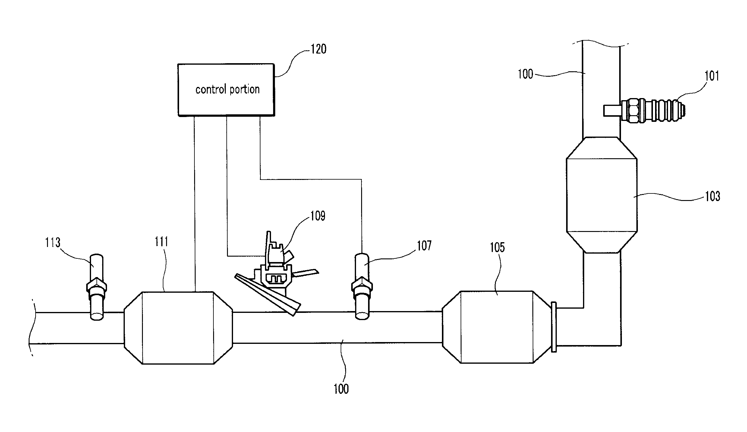
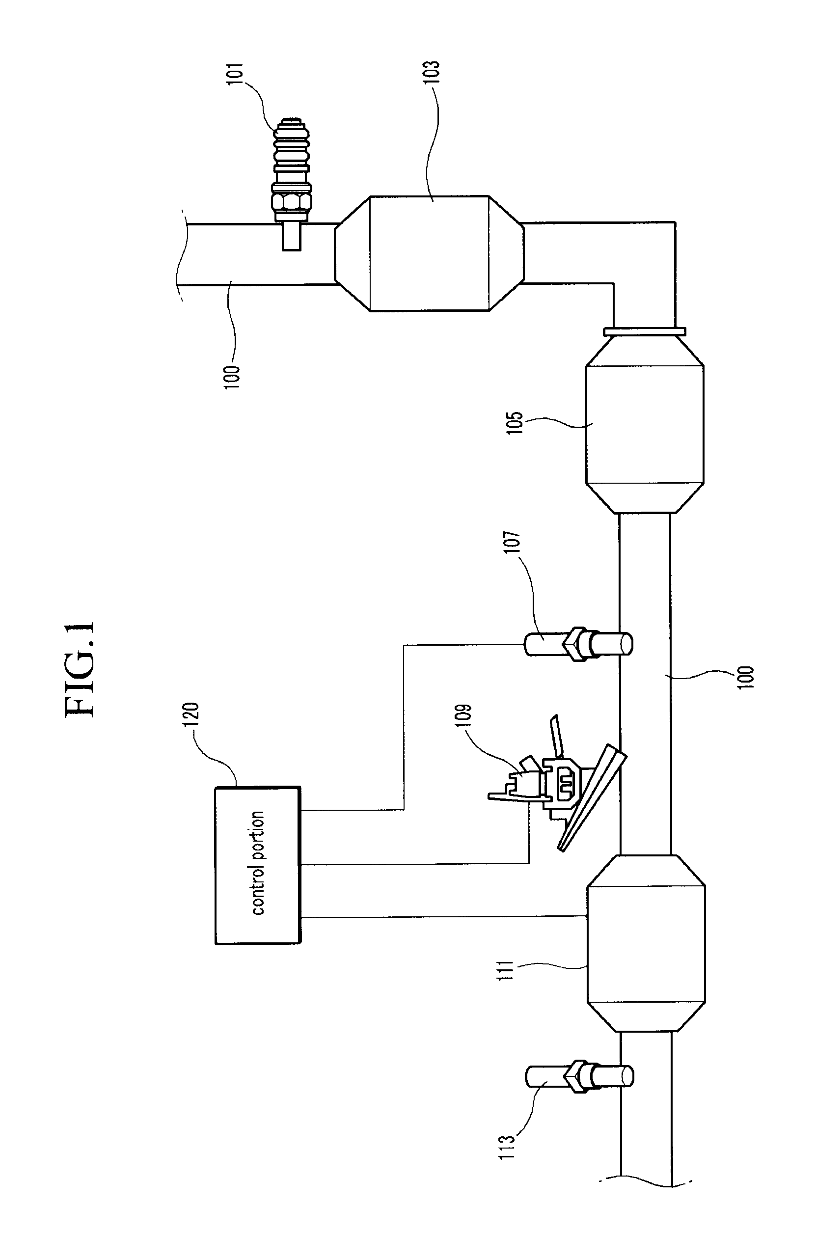
[0019]As shown in FIG. 1, a selective catalytic reduction system according to an exemplary embodiment of the present invention includes a wideband oxygen sensor (linear lambda sensor) 101, a first sensor 107, a selective catalytic reduction apparatus 111, a second sensor 113 and a control portion 120.

[0020]The wideband oxygen sensor 101 is disposed in an exhaust pipe 100 so as to detect oxygen in exhaust gas, and the first sensor 107 is installed at the rear of the wideband oxygen sensor 101 and detects the nitrogen oxide in the exhaust gas. The selective catalytic apparatus 111 is disposed behind the first sensor 107, and includes a urea injector 109. The second sensor 113 is disposed behind the selective catalytic apparatus and detects nitrogen oxide.

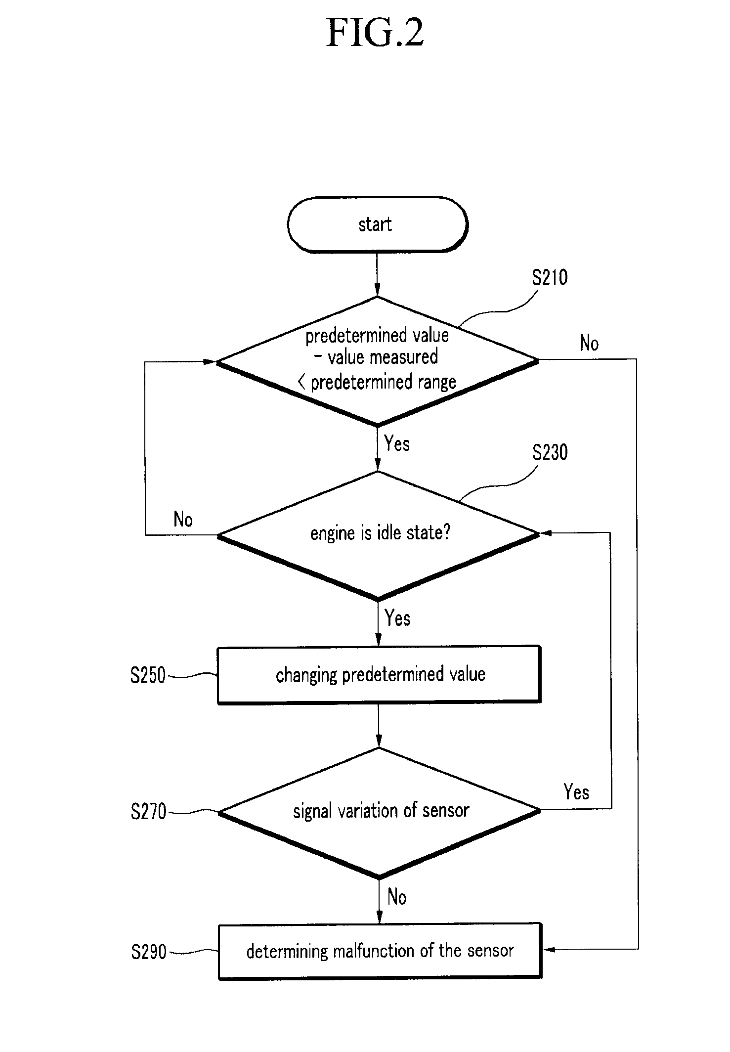
[0021]The control portion 120 determines whether the first sensor 107 is disabled or not on the...


PUM


Abstract

A method for determining malfunction of a nitrogen oxide sensor compares a nitrogen oxide amount detected by the sensor with a predetermined value of nitrogen oxide. If the difference between the predetermined value and the amount detected by the sensor is within a predetermined range, the method determines whether an engine is in a steady state. If the engine is in a steady state, the method changes one or more engine control parameters, thereby varying an actual nitrogen oxide amount. After changing the parameters, the method determines whether the amount detected by the sensor changes. The method determines that the sensor is malfunctioning if the amount detected by the sensor does not change. A selective catalytic reduction system includes a first nitrogen oxide sensor, a selective catalytic reduction apparatus, and a second nitrogen oxide sensor, all disposed in an exhaust pipe. A control portion performs the above-described method.

Description

CROSS-REFERENCE TO RELATED APPLICATION[0001]This application claims priority to, and the benefit of, Korean Patent Application No. 10-2007-0068795, filed in the Korean Intellectual Property Office on Jul. 9, 2007, the entire contents of which are incorporated herein by reference.BACKGROUND OF THE INVENTION[0002]1. Field of Invention[0003]The present invention relates to a method for determining malfunction of a nitrogen oxide sensor, and a selective catalytic reduction system.[0004]2. Description of the Related Art[0005]A typical selective catalytic reduction system cleans nitrogen oxide from a factory exhaust pipe by spraying a urea solution onto it. Recent research has addressed applying such a system to vehicle exhaust pipes.[0006]When using such a system, the amount of nitrogen oxide in exhaust gas needs to be measure, usually by mapping or modeling. This poses a problem in vehicles, since the amount of nitrogen oxide changes with driving conditions or other catalyst devices.[00...

Claims


Application Information

Patent Timeline
IPC IPC(8): F01N11/00F01N3/20F02D41/00
CPCF02D41/146Y02T10/40G01N27/4175F02D41/222F01N9/00F01N11/00
Inventor JUNG, JAE YOON
Owner HYUNDAI MOTOR CO LTD
Why Eureka
Try Eureka