
Refrigerant system with control to address flooded compressor operation

a refrigeration system and compressor technology, applied in adaptive control, lighting and heating apparatus, instruments, etc., can solve the problems of compressor electrical terminal damage, suction pressure can drop to extremely low values, etc., and achieve the effect of reducing the severity of the flooded compressor operation

Active Publication Date: 2009-01-15
CARRIER CORP
View PDF17 Cites 22 Cited by
  • Summary
  • Abstract
  • Description
  • Claims
  • Application Information

AI Technical Summary

Benefits of technology

[0005]The main embodiment of this invention utilizes an SMV, which is a known component placed between the evaporator and the compressor, and means to control the SMV and other associated components to alleviate the severity of the flooded compressor operation.
[0006]To alleviate flooded operation, the control throttles the suction modulation valve to increase the amount of refrigerant quality or superheat entering the compressor, thus decreasing the amount of liquid entering the compressor. The liquid will boil off due to the rise in refrigerant superheat or quality caused by SMV throttling. Also, the SMV throttling will reduce the mass flow of refrigerant entering the compressor (as the SMV throttling causes the reduction in pressure entering the compressor and subsequent reduction in the refrigerant density). As refrigerant enters the compressor it is additionally heated by the heat dissipated by the compressor motor. Since there is less refrigerant entering the compressor if there is throttling, then the refrigerant can be preheated by the motor heat to a higher temperature then if there was no SMV throttling. Additional preheating of the refrigerant by the motor is beneficial, as the heat from the compressor motor will boil off the refrigerant liquid droplets. The SMV throttling also provides additional benefit by increasing the operating pressure ratio (ratio of the compressor discharge pressure to suction pressure) of the compressor (since the suction pressure drops due to throttling while the discharge pressure is only minimally affected by the suction throttling). This increase in the operating pressure results in higher operating temperature during compression, which also helps to boil off any liquid during the compression process). Stated differently, as the compression process begins, the temperature will increase more rapidly then would occur otherwise if there were no throttling, because of a higher pressure ratio operation caused by the throttled SMV.
[0008]The SMV valve can be shut during the off cycle to prevent the compressor being filled with liquid, and then opened (partially or fully) for a very short time at start-up to prevent sudden and intense refrigerant boiling on start up (intense boiling of refrigerant on start up, often called flooded start, is undesirable as it can damage the compressor internal components) Also if the SMV is fully or nearly fully closed on start up, the suction pressure can drop to extremely low values causing damage to compressor electrical terminals. The SMV, after being opened on start-up, will be throttled again as discussed above with a two-phase refrigerant expanding through the SMV.

Problems solved by technology

The SMV valve can be shut during the off cycle to prevent the compressor being filled with liquid, and then opened (partially or fully) for a very short time at start-up to prevent sudden and intense refrigerant boiling on start up (intense boiling of refrigerant on start up, often called flooded start, is undesirable as it can damage the compressor internal components) Also if the SMV is fully or nearly fully closed on start up, the suction pressure can drop to extremely low values causing damage to compressor electrical terminals.

Method used


Image

  • Refrigerant system with control to address flooded compressor operation
  • Refrigerant system with control to address flooded compressor operation
  • Refrigerant system with control to address flooded compressor operation

Examples


Embodiment Construction

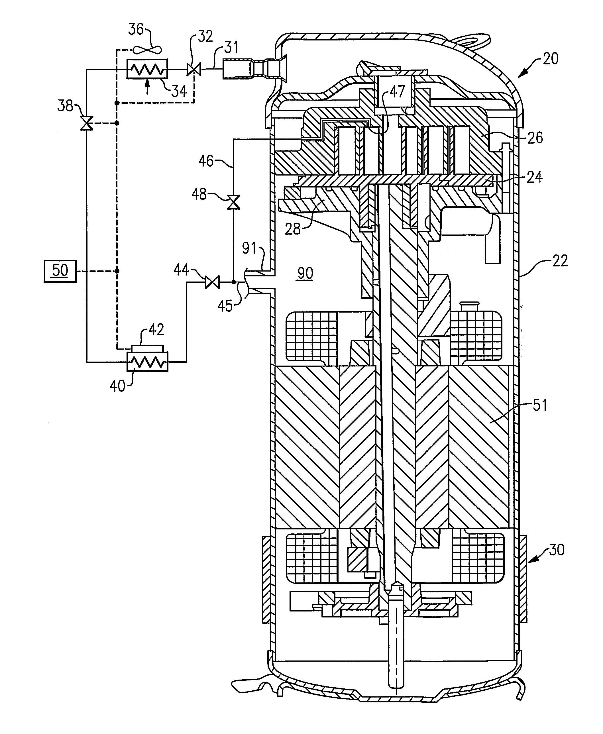
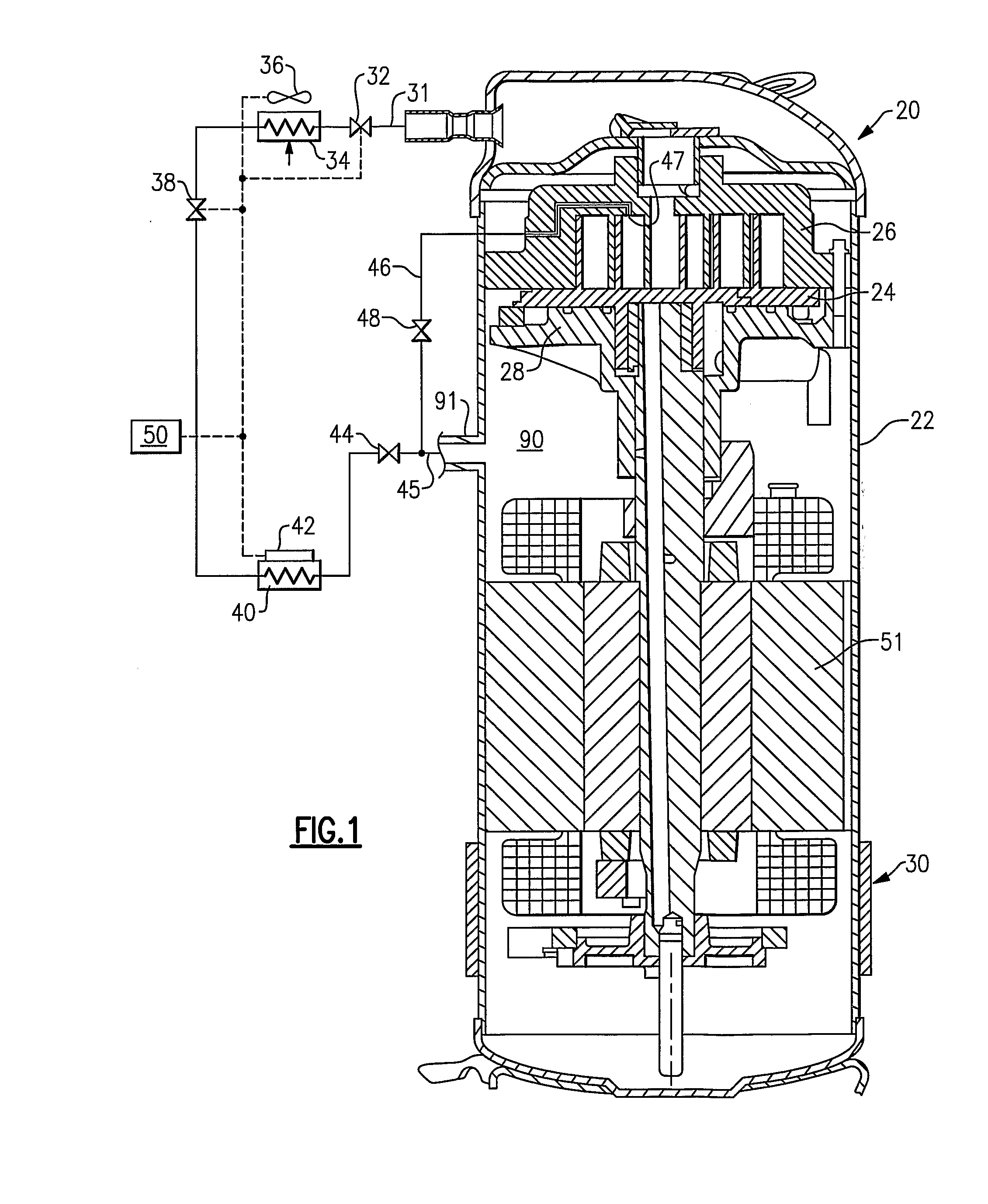
[0016]A refrigerant system 20 is illustrated in FIG. 1, and includes a compressor 22 having an orbiting scroll member 24 and a non-orbiting scroll member 26. A crankcase 28 supports the orbiting scroll 24, as known. While the present invention is disclosed in a scroll compressor, it should be understood that it would extend to any type of compressor, as orbiting scroll member 24 and non-orbiting scroll member 26 can be substituted by other types of compression elements (for example by screws for screw compressors, compression cylinder for reciprocating compressors, or vane and roller arrangement for rotary compressors).

[0017]An optional crankcase heater 30 is shown schematically as being attached to compressor 22, and for a purpose to be described below.

[0018]A discharge line 31 leaving the compressor 22 includes an optional discharge throttling valve 32. Refrigerant passes through the discharge line 31 to a condenser 34 having a condenser fan 36. The refrigerant then passes through...


PUM


Abstract

A suction modulation valve is throttled when conditions in a refrigerant system indicate that an undesirable amount of liquid refrigerant might otherwise be delivered to the compressor. As an example, the throttling would occur at start-up, among other conditions. Throttling the suction modulation valve reduces the amount of refrigerant reaching the compressor and thus ensures that any liquid refrigerant would be likely “boiled off” before raising any problems in the compressor. Other control steps can also be performed to alleviate flooded compressor operation with liquid refrigerant. Such steps, for example, can consist of: actuating heaters, discharge valve throttling, by-passing refrigerant from intermediate compression point back to suction, controlling the speed of the condenser fan can be performed independently or in combination including the suction modulation valve throttling.

Description

RELATED APPLICATIONS[0001]This application claims priority to U.S. Provisional Application No. 60 / 781,249, which was filed Mar. 10, 2006.BACKGROUND OF THE INVENTION[0002]This application relates to a system control technique for eliminating or limiting the amount of liquid refrigerant passing through the compressor. This control technique can, for example, be applied to a suction modulation valve (“SMV”) control.[0003]Refrigerant systems are known, and are utilized in applications such as refrigeration, air conditioning or heat pumps. Typically, a compressor compresses a refrigerant and delivers that refrigerant to a downstream condenser. Refrigerant from the condenser passes through an expansion device, and then through an evaporator. From the evaporator, the refrigerant returns to the compressor.[0004]The refrigerant changes state as it moves through the refrigerant system, and at times it may be in a liquid state, a vapor state or a in a two-phase state where both liquid and vapo...

Claims


Application Information

Patent Timeline
Patent Type & Authority Applications(United States)
IPC IPC(8): F25B45/00F25B1/00G05B15/00
CPCF25B41/043F25B49/02F25B2400/01F25B2500/26Y02B30/743F25B2600/02F25B2600/0261F25B2600/111F25B2600/2517F25B2500/28Y02B30/70F25B41/22
Inventor LIFSON, ALEXANDERSCARCELLA, JASON D.
Owner CARRIER CORP
Learn More