Thermophotovoltaic electrical generation systems

a technology of photovoltaic and electrical generation, applied in the direction of photovoltaics, electrical devices, semiconductor devices, etc., can solve the problems of inefficient system and parasitic system

Inactive Publication Date: 2009-01-15
UNITED TECH CORP
View PDF3 Cites 11 Cited by
  • Summary
  • Abstract
  • Description
  • Claims
  • Application Information

AI Technical Summary

Problems solved by technology

A typical electrical generating system, such as an alternator or generator, has the disadvantage of being a parasitic system wherein the electrical generation system utilizes the primary mover in operation.
Consequently, the electrical generation system is a power drain on the primary mover, resulting in an inefficient system.

Method used


Image

  • Thermophotovoltaic electrical generation systems
  • Thermophotovoltaic electrical generation systems
  • Thermophotovoltaic electrical generation systems

Examples


Embodiment Construction

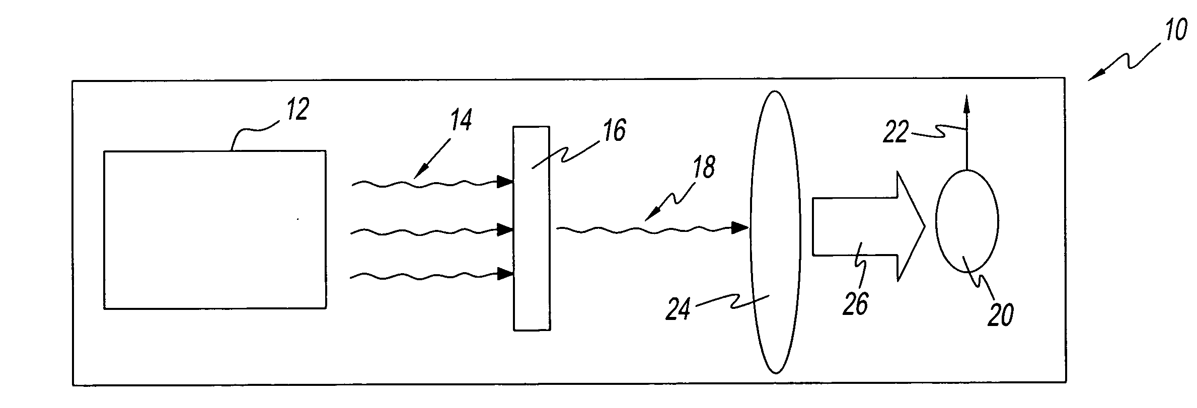
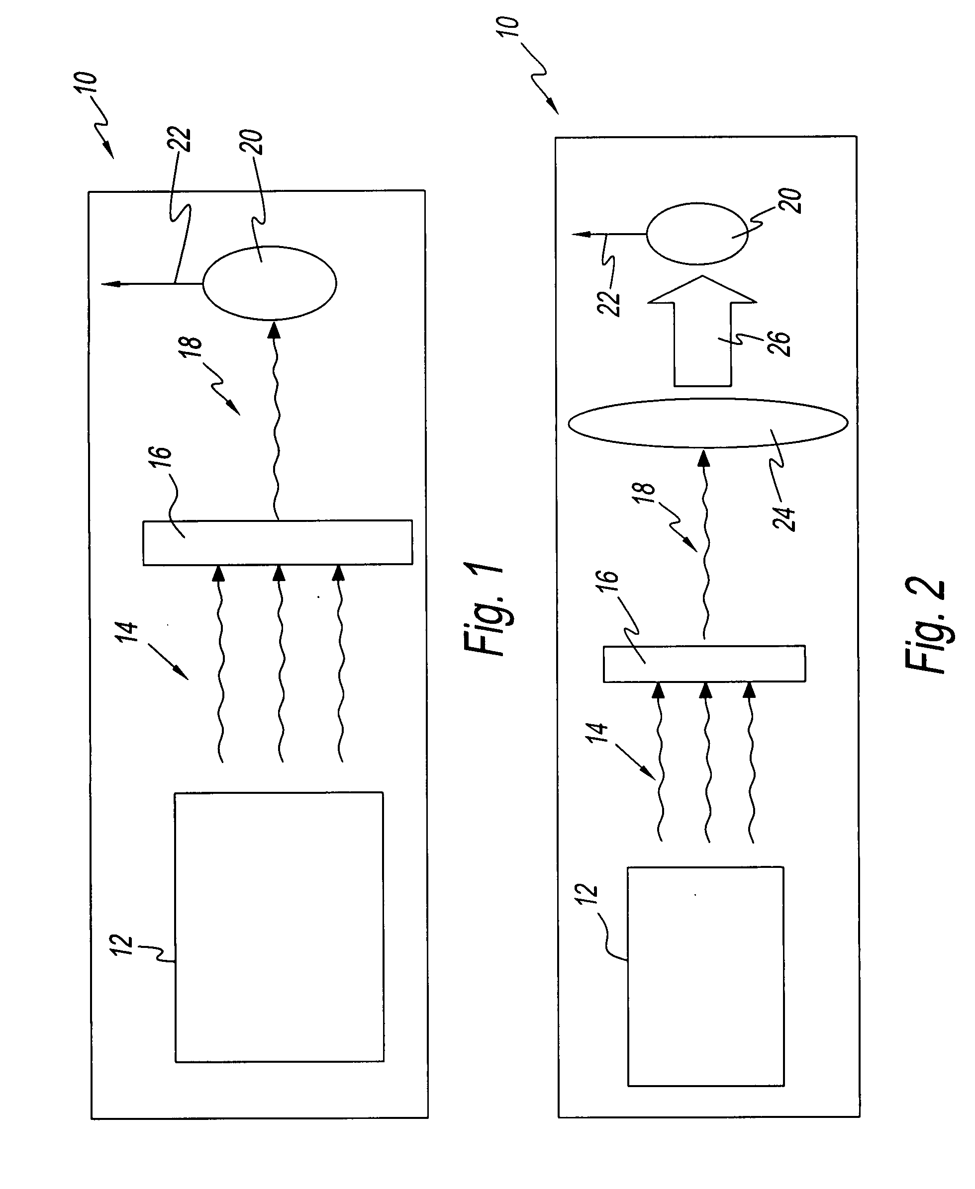
[0013]Referring to the drawings and in particular to FIG. 1, an exemplary embodiment of a thermophotovoltaic (TPV) electrical generation system 10 according to the present disclosure is shown. Advantageously, system 10 converts radiant heat energy into electricity and since system 10 has few moving parts, the system is relatively quiet and requires low maintenance.

[0014]System 10 includes a heat source 12, an optical filter 16, and a themmophotovoltaic device 20.

[0015]Thermophotovoltaic (TPV) device 20 can be any device capable of generating electricity from the heat radiated from heat source 12. For example, TPV device 20 can be a photovoltaic diode cell that generates electricity when exposed to radiant heat of one or more particular wavelengths. In this manner, the photovoltaic diode absorbs radiation of the one or more particular wavelengths and converts the radiated photons into electricity.

[0016]For purposes of discussion, heat source 12 is described herein as a jet engine of ...


PUM


Abstract

A thermophotovoltaic electricity generating system having a heat source generating a thermal emission having a plurality of wavelengths. There is an optical filter filtering the thermal emission into a filtered emission. There is also a thermophotovoltaic device receiving the filtered emission. The thermophotovoltaic device is configured to absorb the thermal emission converting the thermal emission into electricity.

Description

BACKGROUND OF THE INVENTION[0001]1. Field of the Invention[0002]The present disclosure is related to electrical generation systems. More particularly, the present disclosure is related to thermophotovoltaic (TPV) electrical generation systems.[0003]2. Description of Related Art[0004]Many vehicles require a primary mover and an electrical generating system. A typical electrical generating system, such as an alternator or generator, has the disadvantage of being a parasitic system wherein the electrical generation system utilizes the primary mover in operation. Consequently, the electrical generation system is a power drain on the primary mover, resulting in an inefficient system.[0005]Due to environmental concerns and the rising costs of fuel, there is an intrinsic desire to operate vehicles as efficiently as possible. Thus, there is a need for an electrical generating system that is non-parasitic. Even better, there is a need for an electrical generating system that can utilize by-p...

Claims


Application Information

Patent Timeline
Patent Type & Authority Applications(United States)
IPC IPC(8): H01L31/058
CPCH02S10/30H01L31/0232H01L31/02325Y02E10/50
Inventor RADHAKRISHNAN, RAKESHWALKER, CRAIG R.STRIFE, JAMES R.IRISH, JAMES R.
Owner UNITED TECH CORP
Why Eureka
Try Eureka