Thermionic emission device

Active Publication Date: 2010-02-18
TSINGHUA UNIV +1
View PDF4 Cites 12 Cited by
  • Summary
  • Abstract
  • Description
  • Claims
  • Application Information

AI Technical Summary

Problems solved by technology

However, it is hard to assemble a plurality of thermionic electron emission units, and the assembled thermionic emission device cannot realize uniform thermionic emission.
Further, the size of the thermionic emitter using the metal, boride or alkaline earth metal carbonate is large, and thereby limits its application in micro-

Method used


Image

  • Thermionic emission device
  • Thermionic emission device
  • Thermionic emission device

Examples


Embodiment Construction

[0016]References will now be made to the drawings to describe, in detail, embodiments of the present thermionic emission device and method for making the same.

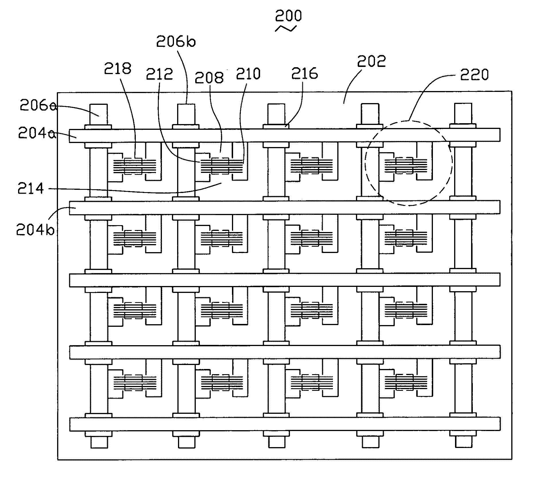
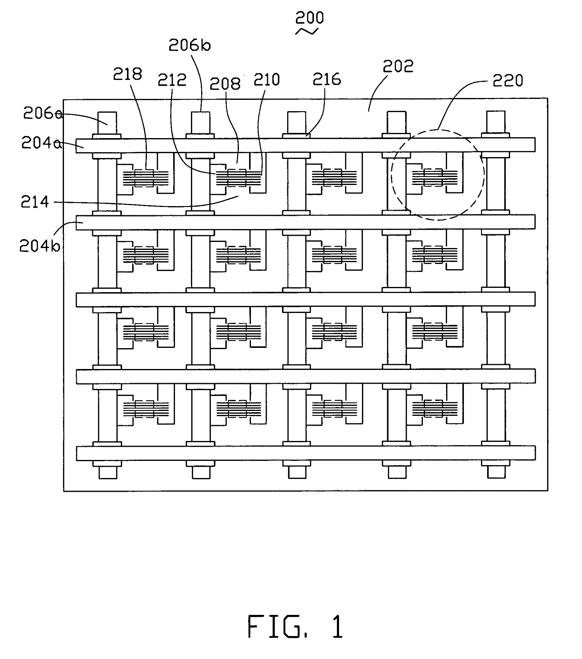
[0017]Referring to FIG. 1, a thermionic emission device 200 includes an insulating substrate 202, and one or more grids 214 located thereon. Each grid 214 includes a first electrode down-lead 204a, a second electrode down-lead 204b, a third electrode down-lead 206a, a fourth electrode down-lead 206b located on the periphery of the gird 214, and a thermionic electron emission unit 220 located in each grid 214. The first electrode down-lead 204a and the second electrode down-lead 204b are parallel to each other. The third electrode down-lead 206a and the fourth electrode down-leads 206b are parallel to each other. Furthermore, a plurality of insulating layers 216 is sandwiched between the first and second electrode down-leads 204a, 204b, and the third and fourth electrode down-leads 206a, 206b to avoid short-circuiting. It is to...


PUM


Abstract

A thermionic emission device includes an insulating substrate, and one or more grids located thereon. Each grid includes a first, second, third and fourth electrode down-leads located on the periphery thereof, and a thermionic electron emission unit therein. The first and second electrode down-leads are parallel to each other. The third and fourth electrode down-leads are parallel to each other. The first and second electrode down-leads are insulated from the third and fourth electrode down-leads. The thermionic electron emission unit includes a first electrode, a second electrode, and a thermionic electron emitter. The first electrode and the second electrode are separately located and electrically connected to the first electrode down-lead and the third electrode down-lead respectively. The thermionic electron emitter includes at least one carbon nanotube wire.

Description

RELATED APPLICATIONS[0001]This application is related to commonly-assigned applications entitled, “METHOD FOR MAKING THERMIONIC ELECTRON SOURCE”, filed **** (Atty. Docket No. US18567); “THERMIONIC ELECTRON SOURCE”, filed **** (Atty. Docket No. US18568); “THERMIONIC EMISSION DEVICE”, filed **** (Atty. Docket No. US18571); “THERMIONIC ELECTRON EMISSION DEVICE AND METHOD FOR MAKING THE SAME”, filed **** (Atty. Docket No. US18569); and “THERMIONIC ELECTRON SOURCE”, filed **** (Atty. Docket No. US17306).BACKGROUND[0002]1. Field of the Invention[0003]The present invention relates to a thermionic emission device adopting carbon nanotubes.[0004]2. Discussion of Related Art[0005]Carbon nanotubes (CNT) are a carbonaceous material and have received much interest since the early 1990s. Carbon nanotubes have interesting and potentially useful electrical and mechanical properties. Due to these and other properties, CNTs have become a significant contributor to the research and development of elec...

Claims


Application Information

Patent Timeline
IPC IPC(8): H01J1/46
CPCH01J1/14H01J2201/30469H01J2201/19
Inventor LIU, PENGLIU, LIANGJIANG, KAI-LIFAN, SHOU-SHAN
Owner TSINGHUA UNIV
Why Eureka
Try Eureka