Plasma Generator With at Least One Non-Metallic Component

a generator and non-metallic technology, applied in the field of plasma generators, can solve the problems of limiting the use of beam profile correction optics, difficult to achieve uniformity in practice, and insufficient use of corrector optics to achieve good beam uniformity, etc., to achieve little or no contaminants, reduce metal contamination levels introduced into workpieces, and little or no contaminants.

Active Publication Date: 2016-03-24
NISSIN ION EQUIP CO LTD
View PDF18 Cites 12 Cited by
  • Summary
  • Abstract
  • Description
  • Claims
  • Application Information

AI Technical Summary

Benefits of technology

[0010]Therefore, there is a need for an improved ion source of an ion implanter that is capable of producing little or no contaminants (e.g., refractory metal compounds) so as to reduce metals contamination levels introduced into a workpiece. Additionally, there is a need for an improved thermionic filament-based plasma electron flood for an ion implanter that is capable of producing little or no contaminants introduced into a workpiece. The present invention provides plasma generators (e.g., ion sources and / or plasma electron floods) for ion implanters that meet such needs, i.e., capable of producing little or no contaminants in the extracted ion beam or electron flux.
[0011]In one aspect, an ion source is provided that has substantially no metallic materials exposed to the source plasma in the ion source. This can be achieved by selecting certain materials to fabricate one or more ion source components having surfaces that are in direct contact with the source plasma. Such a design is applicable to ion sources presently being used in the field and enables a significant improvement in ion-implanted device yields.
[0016]In another aspect, a plasma electron flood having a thermionic filament is provided that has substantially no metallic materials exposed to the plasma in the flood. This can be achieved by selecting certain materials to fabricate one or more flood components having surfaces that are in direct contact with the flood plasma. Such a design is applicable to plasma electron floods presently being used in the field and enables a significant improvement in ion-implanted device yields.

Problems solved by technology

However, such uniformity is difficult to achieve in practice.
Using corrector optics is generally not sufficient to create good beam uniformity if the beam is greatly non-uniform upon extraction from the ion source or if aberrations are induced by space-charge loading and / or beam transport optics.
These features attempt to produce a uniform profile during beam extraction while limiting the use of beam profile-correcting optics.
However, such metallic ions sources can produce ion beams containing contaminants (e.g., refractory metal compounds) that are difficult to remove even with the aid of sophisticated mass selection approaches.
If the workpiece is a silicon wafer used in the fabrication of integrated circuits, the presence of even a few parts-per-million (ppm) of the contaminants can negatively affect yield.
Since ion beams are composed of positively-charged ions, positive charge can build up on an implanted workpiece, potentially damaging the devices which populate the workpiece.
In a typical plasma electron flood, due to its proximity to the substrate, tungsten evaporated from the hot filament can contaminate the substrate during flood operation.
If the workpiece is a silicon wafer used in the fabrication of integrated circuits, the presence of even a few parts-per-million (ppm) of refractory metal contaminants can negatively affect yield.
While such floods may not produce refractory metal contamination, they are expensive, relatively large, and complex to design and operate.

Method used


Image

  • Plasma Generator With at Least One Non-Metallic Component
  • Plasma Generator With at Least One Non-Metallic Component
  • Plasma Generator With at Least One Non-Metallic Component

Examples


Embodiment Construction

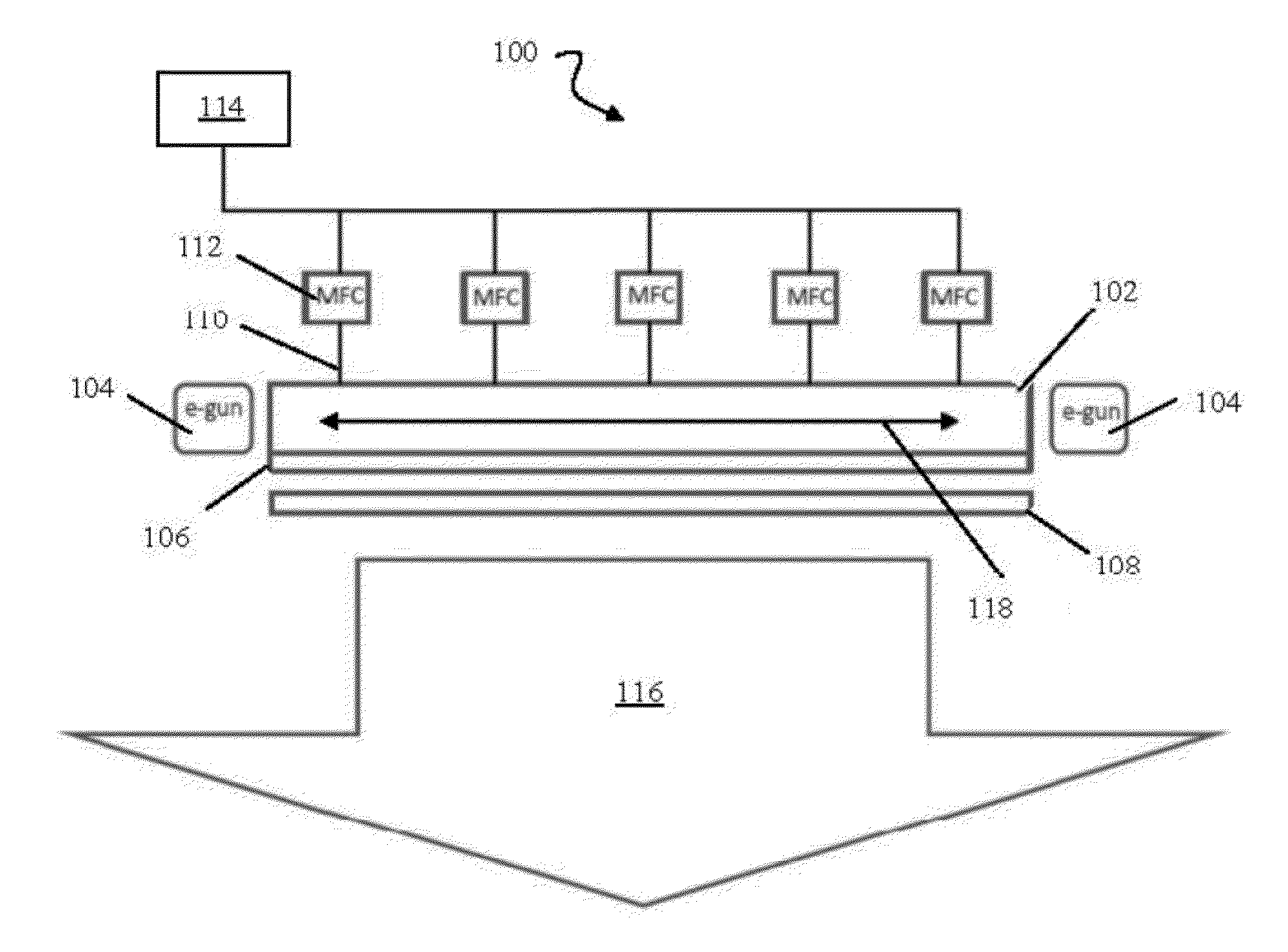
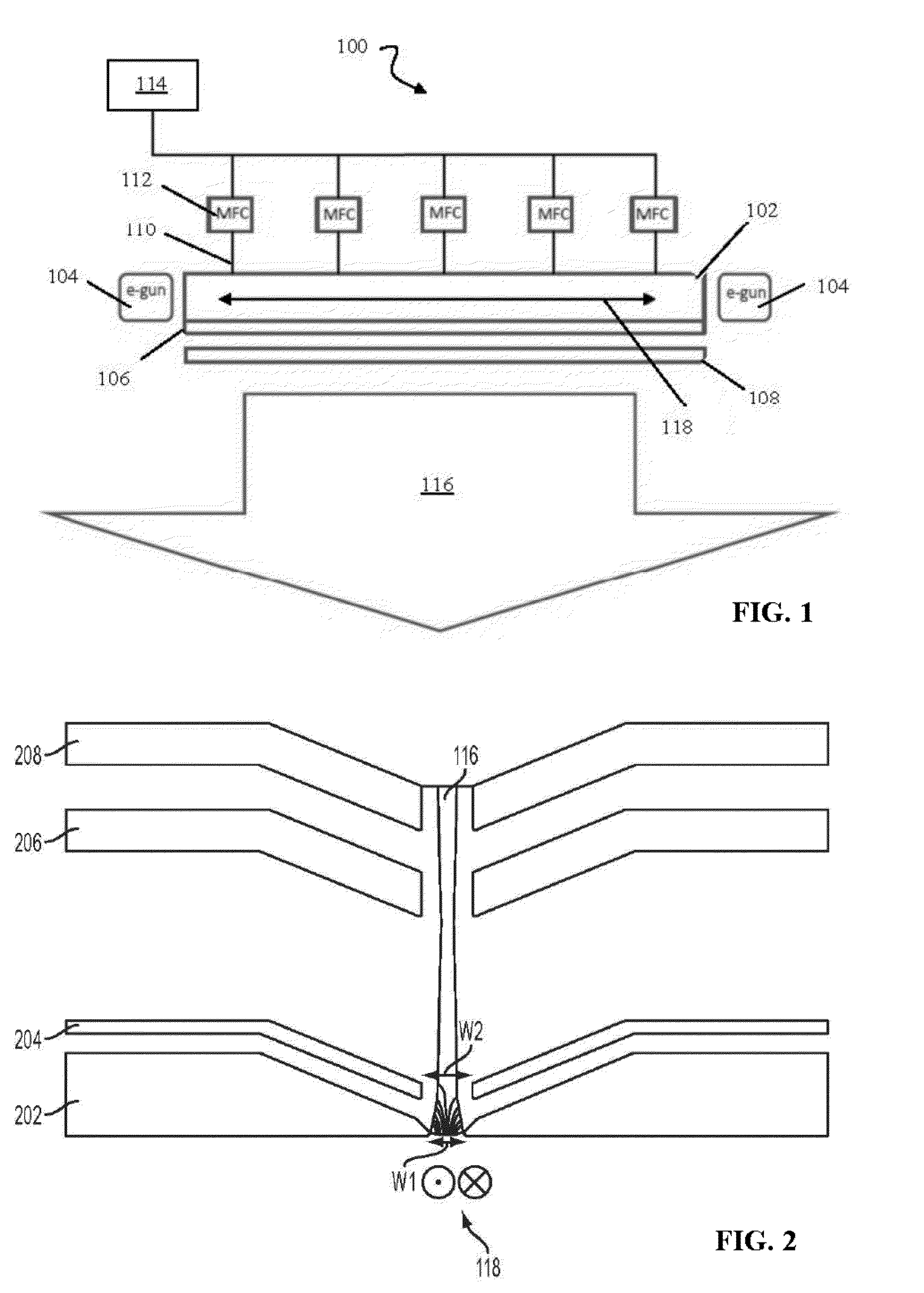
[0062]FIG. 1 shows a schematic diagram of an exemplary ion source, according to embodiments of the present invention. The ion source 100 can be configured to produce an ion beam for transport to an ion implantation chamber that implants the ion beam into, for example, a semiconductor wafer. As shown, the ion source 100 includes an ionization chamber 102 defining a longitudinal axis 118 along the long dimension of the ionization chamber 102, a pair of electron guns 104, a plasma electrode 106, a puller electrode 108, a gas delivery system comprising a plurality of gas inlets 110 and a plurality of mass flow controllers (MFCs) 112, a gas source 114, and a resultant ion beam 116. In operation, gaseous material from the gas source 114 is introduced into the ionization chamber 102 via the gas inlets 110. The gas flow through each of the gas inlets 110 can be controlled by the respective mass flow controllers 112 coupled to the inlets 110. In the ionization chamber 102, a primary plasma f...


PUM

PropertyMeasurementUnit
lengthaaaaaaaaaa
lengthaaaaaaaaaa
source voltageaaaaaaaaaa

Abstract

A plasma generator for an ion implanter is provided. The plasma generator includes an ionization chamber for forming a plasma that is adapted to generate a plurality of ions and a plurality of electrons. An interior surface of the ionization chamber is exposed to the plasma and constructed from a first non-metallic material. The plasma generator also includes a thermionic emitter including at least one surface exposed to the plasma. The thermionic emitter is constructed from a second non-metallic material. The plasma generator further includes an exit aperture for extracting at least one of the plurality of ions or the plurality of electrons from the ionization chamber to form at least one of an ion beam or an electron flux. The ion beam or the electron flux comprises substantially no metal. The first and second non-metallic materials can be the same or different from each other.

Description

CROSS REFERENCE TO RELATED APPLICATIONS[0001]This application is a continuation-in-part of U.S. Ser. No. 13 / 835,475, filed Mar. 15, 2013. This application also claims the benefit of and priority to U.S. Provisional Patent Application Ser. Nos. 62 / 090,017 and 62 / 189,917, filed Dec. 10, 2014 and Jul. 8, 2015, respectively. The contents of these applications are owned by the assignee of the instant application and are incorporated herein by reference in their entirety.FIELD OF THE INVENTION[0002]The invention relates generally to plasma generators for ion implanters, and more particularly, to plasma generators with one or more components constructed from non-metallic material(s).BACKGROUND OF THE INVENTION[0003]Ion implantation has been a critical technology in semiconductor device manufacturing and is currently used for many processes including fabrication of the p-n junctions in transistors, particularly for CMOS devices such as memory and logic chips. By creating positively-charged ...

Claims


Application Information

Patent Timeline
Patent Type & Authority Applications(United States)
IPC IPC(8): H01J27/20H01J27/02
CPCH01J27/02H01J27/20C23C14/48H01J27/022H01J27/205H01J37/08H01J37/3171H01J2237/022H01J2237/082H01J2237/31701H01J2237/31705H01J37/00
Inventor HORSKY, THOMAS, N.HAHTO, SAMI, K.
Owner NISSIN ION EQUIP CO LTD
Why Eureka
Try Eureka