Fibre Optic Dosimeter

a fiber optic and dosimeter technology, applied in the field of dosimeters, can solve the problems of few if any, suited to use in a dosimeter that satisfies the demands of contemporary radiation therapy techniques, generation of cerenkov (or cherenkov) radiation in, transmission of cerenkov radiation along, etc., and achieves the effect of reducing or preventing the entry of cerenkov radiation

Inactive Publication Date: 2009-01-15
THE UNIV OF SYDNEY
View PDF14 Cites 58 Cited by
  • Summary
  • Abstract
  • Description
  • Claims
  • Application Information

AI Technical Summary

Benefits of technology

[0013]According to a first aspect of the present invention, there is provided a dosimeter for radiation fields, the dosimeter comprising a scintillator, a light pipe having a first end in optical communication with the scintillator, and a detector to detect light output from a second end of the light pipe and to provide an output indicative of the...

Problems solved by technology

While a range of devices suitable for detecting radiation fields are known, few if any, are suited to use in a dosimeter that satisfies the demands of contemporary radiation therapy techniques.
An identified problem with fibre optic dosimeters is the generation of Cerenkov (or Cherenkov) radiation in, and transmission of the Cerenkov radiation along, the light pipe.
A problem with the use of signal processing to discriminate between Cerenkov radiation and the signal from a scintillator,...

Method used


Image

  • Fibre Optic Dosimeter
  • Fibre Optic Dosimeter
  • Fibre Optic Dosimeter

Examples


first embodiment

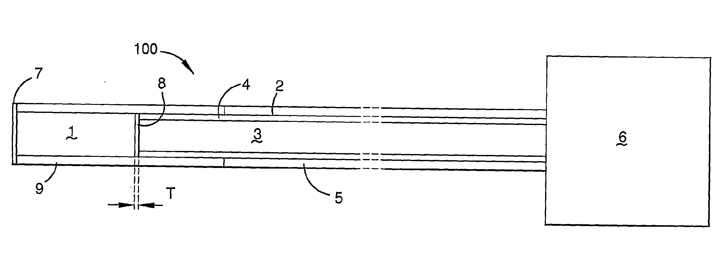
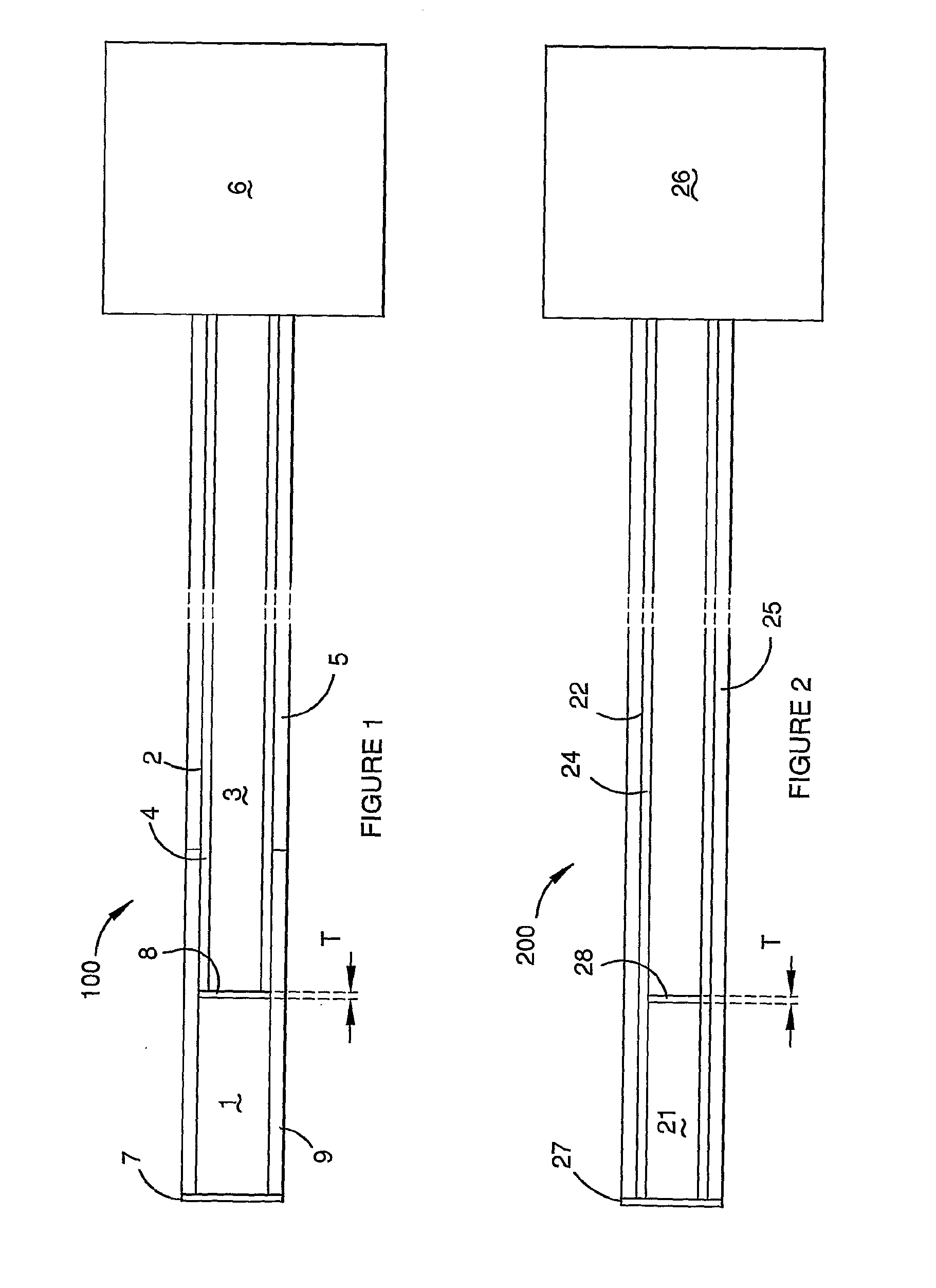
[0060]Referring to FIG. 1 of the accompanying drawings, a schematic view of a dosimeter is generally referenced by arrow 100.

[0061]The dosimeter 100 includes a scintillator 1 in communication with a light pipe, which is suitably an optical fibre 2. Suitable scintillators for use in the present invention include anthracene-doped PolyVinyl Toluene (PVT), Polystyrene (PS) or Poly(methyl)methacrylate (PMMA) based scintillators, or scintillating fibres with a polystyrene-based core and a poly(methyl)methacrylate-based cladding, both available from Saint-Gobain of France and elsewhere.

[0062]The fibre 2 has a core 3, a cladding 4 and in the embodiment shown also includes a buffer tubing 5. The buffer tubing 5 may be omitted, both in this embodiment and in the other embodiments of the present invention described herein. The fibre 2 may be a polymer fibre.

[0063]The fibre 2 is connected to a photodetector 6. The photodetector 6 may be any suitable detector, including a photomultiplier or phot...

second embodiment

[0071]FIG. 2 shows a dosimeter, which is generally referenced by arrow 200, which may also have particular application to brachytherapy, and may share the same combination of features described herein above as advantageous in relation to the dosimeter 100 shown in FIG. 1. The dosimeter 200 shown in FIG. 2 has a scintillator 21, which will typically have a diameter of less than 1 millimetre for brachytherapy applications. The scintillator 21 may have a length to diameter ratio in the range of 1:1 to 5:1 in order to provide an appropriate balance between signal strength and spatial resolution for some applications. In FIG. 2, the ratio is approximately 3.5:1 and in FIG. 1 the ratio was approximately 2.6:1. The examples provided in FIGS. 1 and 2 show scintillators in the most preferred range of dimensions as presently contemplated, namely having a length to diameter (or width) ratio in the range of 2:1 to 4:1. Using a scintillator within this range may provide an optimal balance betwee...

third embodiment

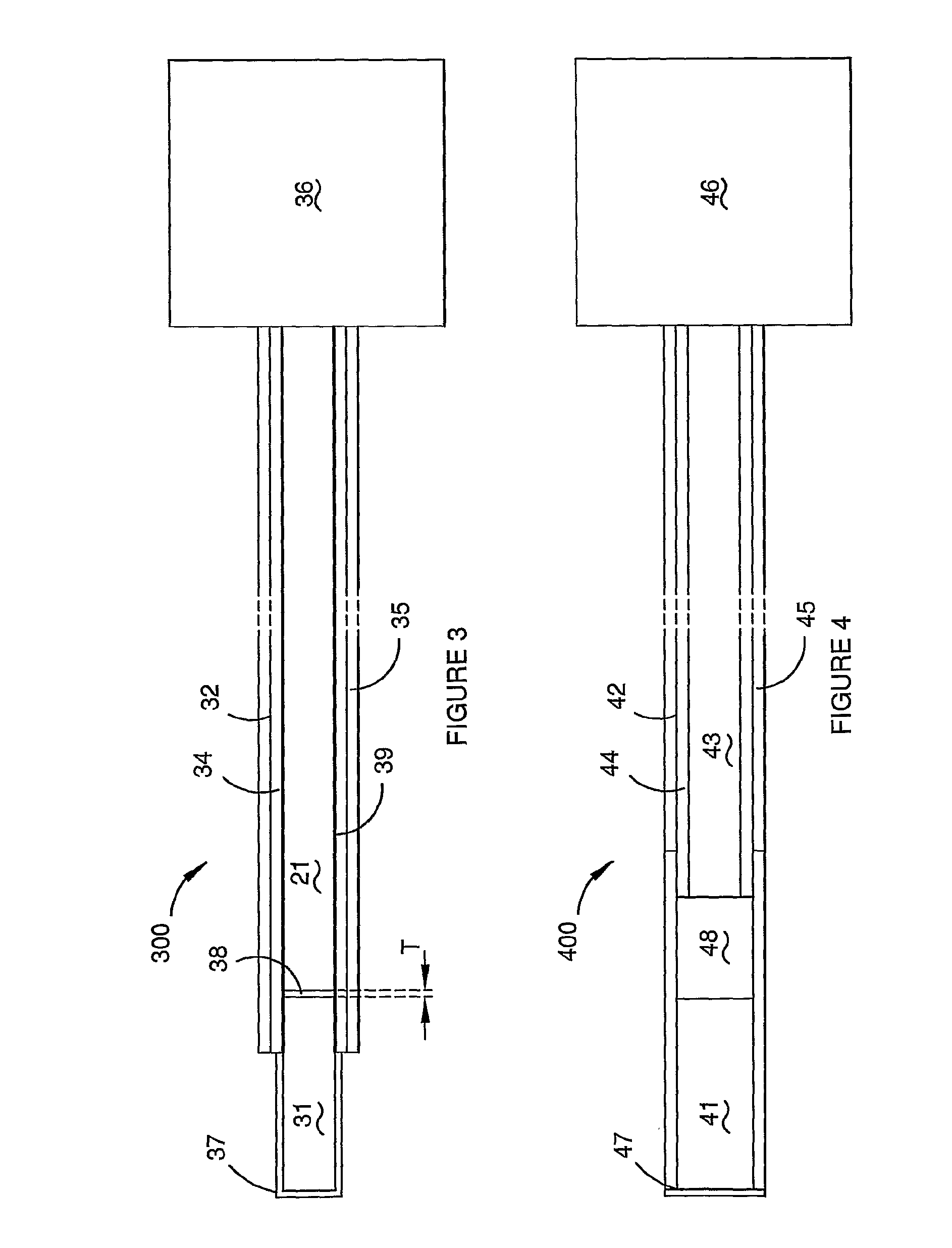
[0075]FIG. 3 shows a schematic representation of a dosimeter in accordance with the present invention, which is generally referenced by arrow 300. The dosimeter 300 includes a scintillator 31 and an optical fibre 32 having a core 33, cladding 34 and optional buffer tubing 35. The cladding 34 may be a sheath. A reflector 37 is provided at the end of the scintillator 31 and about the sides of the scintillator 31. Extending the reflector 37 to around the sides of the scintillator 31 will provide advantage when the numerical aperture of the fibre 32 is larger than the numerical aperture of the scintillator 31, due to increasing the numerical aperture of the scintillator 31. An anti-reflection coating 38 is provided at the interface of the scintillator 31 with the fibre 32. The combination of using a small scintillator and a fibre with a large core and high numerical aperture may also be used for the dosimeter 300.

[0076]The fibre 32, which is connected to a photo detector 36 has a hollow...


PUM


Abstract

A dosimeter (100) for radiation fields is described. The dosimeter includes a scintillator (1) a light pipe (2) having a first end in optical communication with the scintillator (1) and a light detector (6). The light pipe (2) may have a hollow core (3) with a light reflective material about the periphery of the hollow core (3). The dosimeter (100) may further include a light source (61) that generates light for use as a calibrating signal for a measurement signal and/or for use to check the light pipe (2).

Description

TECHNICAL FIELD[0001]The present invention relates to dosimeters for measuring the dose from radiation fields and a method of manufacturing a dosimeter. In particular, the present invention relates to the field of fibre optic dosimeters.BACKGROUND[0002]While a range of devices suitable for detecting radiation fields are known, few if any, are suited to use in a dosimeter that satisfies the demands of contemporary radiation therapy techniques. In order to accommodate contemporary therapy techniques, there is a need for a dosimeter that can accurately verify the radiation treatment therapy, accommodate time dependent therapy techniques such as intensity modulated radiation therapy, and also accommodate precision therapy techniques such as stereotactic radiosurgery. The dosimeter should be able to provide high spatial resolution, while retaining the ability to integrate the total dose over the whole treatment period. The dosimeter should also provide a frequently updated reading of the...

Claims


Application Information

Patent Timeline
IPC IPC(8): H05B33/00
CPCG01T1/023G01T1/40G01T1/161
Inventor FLEMING, SIMONELSEY, JUSTINLAW, SUSANSUCHOWERSKA, NATALKALAMBERT, JAMILMCKENZIE, DAVID ROBERT
Owner THE UNIV OF SYDNEY
Why Eureka
Try Eureka