Antenna Apparatus

a technology of antenna and antenna body, which is applied in the direction of antenna, antenna details, electrical equipment, etc., can solve the problems of radio interference, distorted radiation pattern radiated from the antenna,

Inactive Publication Date: 2009-01-15
SONY CORP
View PDF3 Cites 17 Cited by
  • Summary
  • Abstract
  • Description
  • Claims
  • Application Information

AI Technical Summary

Benefits of technology

[0018]It is desirable to provide a superior antenna apparatus having a patch antenna configuration configured by arranging a rad...

Problems solved by technology

A planar antenna, such as a patch antenna, has problems that a surface wave (an electromagnetic wave propagated on the surface of a ground conductor plate) occurs on an antenna substrate, the surface wave is propagated to the end portion of the antenna substrate, and an unwanted electromagnetic wave (an unwanted electromagnetic wave resulting from a surface wave) is radiated fr...

Method used


Image

  • Antenna Apparatus
  • Antenna Apparatus
  • Antenna Apparatus

Examples


Embodiment Construction

[0041]An embodiment of the present invention will be described below with reference to the drawings.

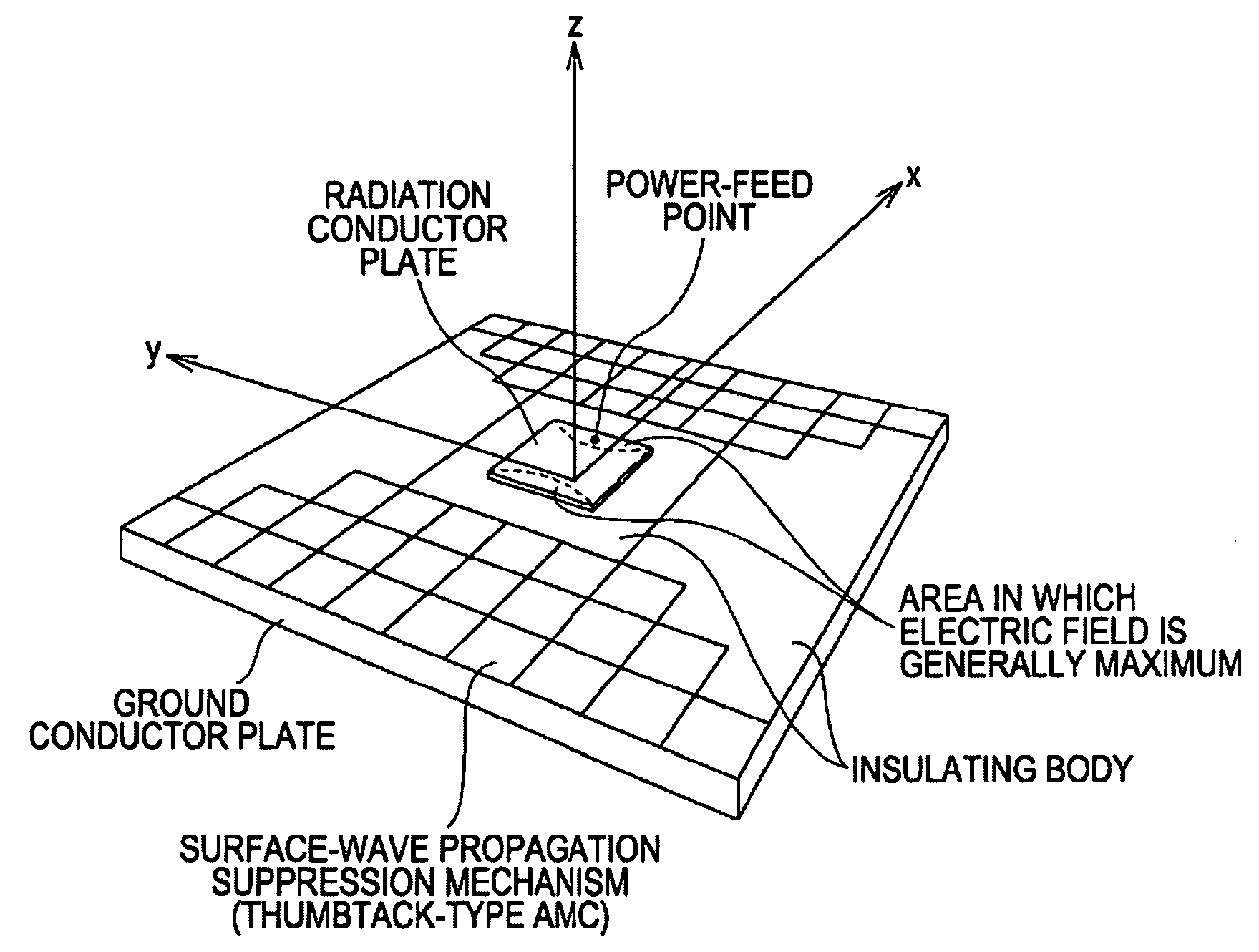
[0042]FIG. 1 shows the configuration of an antenna apparatus according to an embodiment of the present invention. The antenna apparatus shown in the figure is configured in such a manner that a surface-wave propagation suppression mechanism is disposed in the area surrounding a patch antenna unit in which a radiation conductor and a ground conductor plate are arranged so as to face each other with an insulating material disposed therebetween.

[0043]In the patch antenna unit, a power-feed point is provided at a position slightly offset from the center of the radiation conductor. As electrical current components in the offset direction of the power-feed point, that is, in the x-axis direction in the figure, increase, a radiation electric field is generated, and a standing wave is excited. Then, by adjusting the offset length, it is possible to achieve matching at 50 ohms. In the example ...


PUM


Abstract

An antenna apparatus includes a patch antenna unit in which a radiation conductor and a ground conductor plate are arranged so as to face each other with an insulating material disposed therebetween, a power-feed point is provided at a position slightly offset from the center of the radiation conductor, and a high-frequency electric field is supplied between the radiation conductor and the ground conductor plate; a surface-wave propagation suppression area in which a surface-wave propagation suppression mechanism for suppressing surface-wave propagation is mounted in an outer surrounding area in the offset direction of the power-feed point in which an electric-field intensity is generally maximum within the end portion of the radiation conductor plate; and an insulating area in which an electric-field intensity between the radiation conductor plate and the ground conductor plate is relatively low and the surface-wave propagation suppression mechanism is not arranged.

Description

CROSS REFERENCES TO RELATED APPLICATIONS[0001]The present invention contains subject matter related to Japanese Patent Application JP 2007-180354 filed in the Japanese Patent Office on Jul. 9, 2007, the entire contents of which are incorporated herein by reference.BACKGROUND OF THE INVENTION[0002]1. Field of the Invention[0003]The present invention relates to an antenna apparatus used to transmit and receive wireless signals and, particularly, relates to an antenna apparatus having a patch antenna configuration in which a radiation conductor and a ground conductor plate are arranged so as to face each other with an insulating material disposed therebetween.[0004]More particularly, the present invention relates to an antenna apparatus in which radiation of unwanted electromagnetic waves resulting from surface waves generated on an antenna substrate is suppressed, and distortion of a radiation pattern is thereby reduced and, particularly, relates to an antenna apparatus in which AMC (...

Claims


Application Information

Patent Timeline
IPC IPC(8): H01Q9/04H01Q1/00
CPCH01Q9/0407H01Q15/008H01Q15/14
Inventor KURODA, SHINICHI
Owner SONY CORP
Why Eureka
Try Eureka