Light emission control circuit, light emission control method, flat illuminating device, and liquid crystal display device having the same device

a technology of light emission control and control circuit, which is applied in the direction of static indicating devices, instruments, optics, etc., can solve the problems of large-scale circuit configuration, increase in costs, and large-scale configuration of power source circuits, so as to simplify power source circuits and reduce costs and power consumption

Active Publication Date: 2009-01-15
NEC LCD TECH CORP
View PDF5 Cites 49 Cited by
  • Summary
  • Abstract
  • Description
  • Claims
  • Application Information

AI Technical Summary

Benefits of technology

[0020]In view of the above, it is an exemplary object of the present invention to provide a light emission control circuit capable of simplifying a power source circuit and reducing costs and power consumption, a light emission control method using the above circuit, a flat illuminating device, and a liquid crystal display device equipped with the flat illuminating device.

Problems solved by technology

However, the conventional technology presents a problem in that, in the case of using, as a light source, three kinds of LEDs (red LED, green LED, and blue LED), three sets of circuits to supply a constant current, which causes the configurations of a power source circuit to be made large-scaled, thus causing a rise in costs.
In the case of the backlight device of a large-sized liquid crystal display device and a large number of LEDs is used, if a voltage boosting circuit or control circuit for every color is to be mounted, it causes the circuit to be large-scaled, which leads to an increase in costs.
However, the conventional technology has also problems.
That is, when this conventional technology is applied to a backlight device, a forward voltage changes depending on a current fed to each of the LEDs 201a and, as a result, when there is a difference between currents If1 and If2 flowing from two sets of the LED group, current consumption wastefully increases.
However, in the Patent References 3, 4, and 5 a constant current circuit is provided, for example, in every LED or in every light emitting unit (light emitting device), which causes an increase in power consumption.
Therefore, the problem to be solved is that the above conventional technology causes a power source circuit to become large-scaled, which leads to an increase in costs and in power consumption.

Method used


Image

  • Light emission control circuit, light emission control method, flat illuminating device, and liquid crystal display device having the same device
  • Light emission control circuit, light emission control method, flat illuminating device, and liquid crystal display device having the same device
  • Light emission control circuit, light emission control method, flat illuminating device, and liquid crystal display device having the same device

Examples


first exemplary embodiment

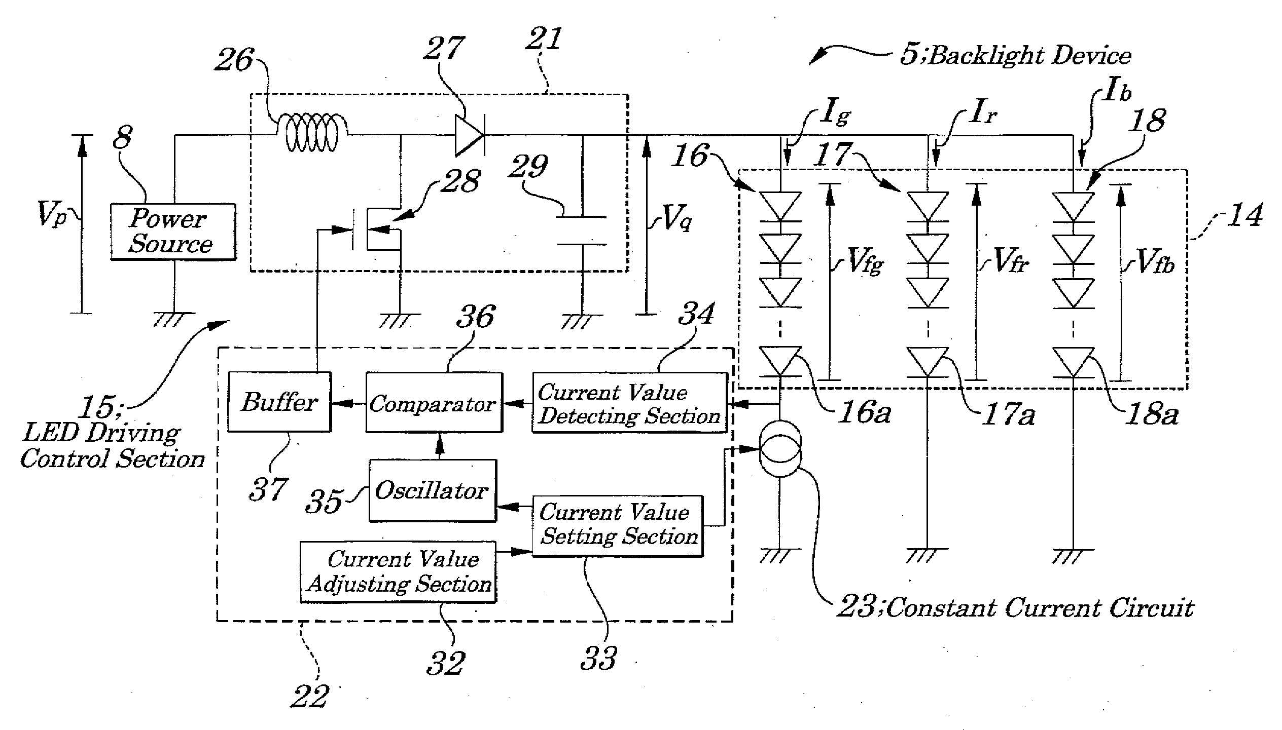
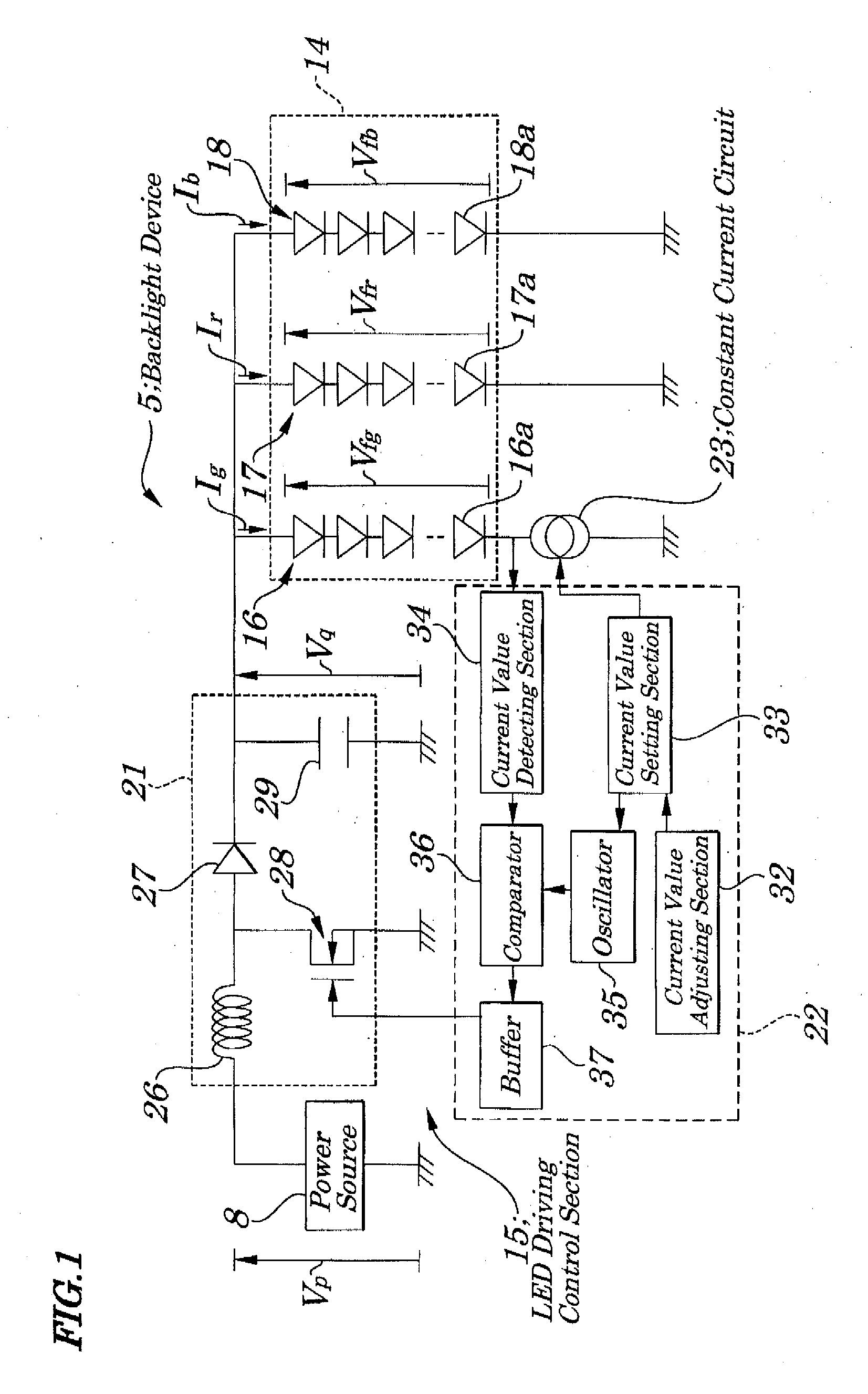
[0051]FIG. 1 is a schematic block diagram showing electrical configurations of a backlight of the first exemplary embodiment of the present invention. FIG. 2 is a block diagram showing a liquid crystal display device equipped with the backlight of FIG. 1. FIG. 3 is an explanatory diagram of operations of the backlight of FIG. 1, and FIG. 4 is an explanatory diagram of operations of an LED driving control section of the backlight of FIG. 1.

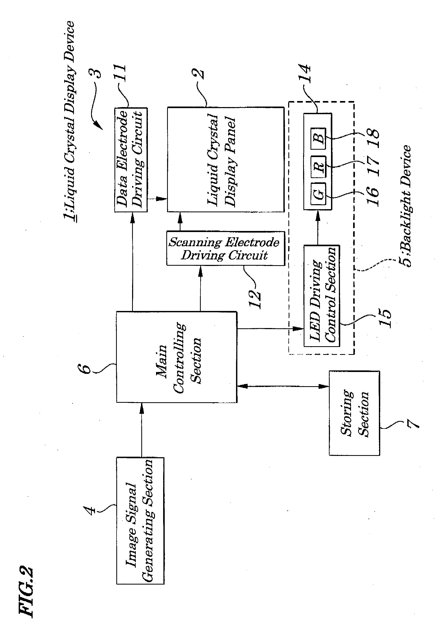
[0052]The liquid crystal display device 1, as shown in FIG. 2, includes a liquid crystal display panel 2, an LCD (Liquid Crystal Display) driving circuit section 3, an image signal generating section 4 to generate a corresponding image signal based on image data fed from the outside, a backlight device 5 to supply illuminating light to the liquid crystal display panel 2, a main controlling section 6 made up of, for example, a CPU (Central Processing Unit) to perform specified control functions and computation function, a storing section 7 made up o...

second exemplary embodiment

[0074]FIG. 5 is a schematic block diagram showing electrical configurations of a backlight device according to the second exemplary embodiment. FIG. 6 is a diagram showing operations of the backlight device of FIG. 5. The configurations of the second exemplary embodiment differ greatly from those of the first exemplary embodiment in that currents flowing through each LED group are switched so that chromaticity can be adjusted. The configurations other than the above are almost the same as those of the first exemplary embodiment and, therefore, in FIG. 5, the same reference numbers are assigned to the same configurations as those in FIG. 1 and their descriptions are simplified accordingly.

[0075]The backlight device 5A of the liquid crystal display device of the second exemplary embodiment, as shown in FIG. 5, has a light source unit 14, an LED driving control section 15A to drive and control each of the LEDs making up the light source unit 14 and an optical member group. The light so...

third exemplary embodiment

[0085]FIG. 7 is a schematic block diagram showing electrical configurations of a backlight device according to the third exemplary embodiment of the present invention. The configurations of the third exemplary embodiment differ greatly from those of the second exemplary embodiment in that a chromaticity sensor is newly provided and the backlight device is so configured as to control a current flowing through each LED. The configurations other than the above are almost the same as those of the second exemplary embodiment and, therefore, in FIG. 7, the same reference numbers are assigned to the same configurations as those in FIG. 5 and their descriptions are simplified accordingly.

[0086]The backlight device 5B of the liquid crystal display device of the third exemplary embodiment, as shown in FIG. 7, includes a light source unit 14, LED driving control section 15B to drive and control each LED making up the light source unit 14, and an optical member group. The LED driving control se...


PUM

PropertyMeasurementUnit
frequencyaaaaaaaaaa
currentaaaaaaaaaa
forward voltageaaaaaaaaaa

Abstract

There is provided a light emission control circuit being capable of simplifying a power source circuit reducing costs and power consumption. A constant current circuit is serially connected to a specified light emitting device group out of a plurality of light emitting device groups and a power source circuit supplies power to each light emitting device group and a current detecting unit detects a current flowing through a specified light emitting device group and a power control unit controls a power source circuit based on a pre-set current value and on a detected value.

Description

INCORPORATION BY REFERENCE[0001]This application is based upon and claims the benefit of priority from Japanese Patent Application No. 2007-179090, filed on Jul. 6, 2007, the disclosure of which is incorporated herein in its entirely by reference.BACKGROUND OF THE INVENTION[0002]1. Field of the Invention[0003]The present invention relates to a light emission control circuit, light emission control method, flat illuminating device, and liquid crystal display device equipped with the flat illuminating device and more particularly to the light emission control circuit, light emission control method, flat illuminating device, and liquid crystal display device equipped with the flat illuminating device, which are configured to control driving of a light source made up of a light emitting device such as an LED (light-emitting diode).[0004]2. Description of the Related Art[0005]Conventionally, a display device using a CRT (Cathode Ray Tube) has been used for displaying images, for example,...

Claims


Application Information

Patent Timeline
Patent Type & Authority Applications(United States)
IPC IPC(8): G02F1/13357G09G3/32G02F1/133G09G3/20G09G3/34G09G3/36H01L33/00H05B37/02H05B44/00
CPCH05B33/0815H05B45/38H05B45/28H05B45/3725
Inventor HONBO, NOBUAKI
Owner NEC LCD TECH CORP
Why Eureka
Try Eureka