


Quick Research
Generate reliable direction feasibility study reports for your R&D in just a few steps.

Technical Q&A
Discover and master advanced knowledge NOW. Basics, ideas, possibilities, all at once.

Find Solutions
As an expert in R&D theories, this can generate solutions to your technical problems instantly.

Evaluate Feasibility
Analyze your overall solution with one click, know your potential R&D risks in advance.

Monitor Landscape
Get weekly tech updates, stay abreast of the latest tech innovations and key insights.
Color filter and photomask to be employed for the manufacture of color filter
a color filter and color filter technology, applied in the field of color filters for liquid crystal display devices, can solve the problems of adverse effects on the quality of display, decrease of contrast, and limitation of the density of the photo-spacer, and achieve the effect of excellent press resistan
- Summary
- Abstract
- Description
- Claims
- Application Information
AI Technical Summary
Benefits of technology
Problems solved by technology
Method used
Image

Examples
example 1
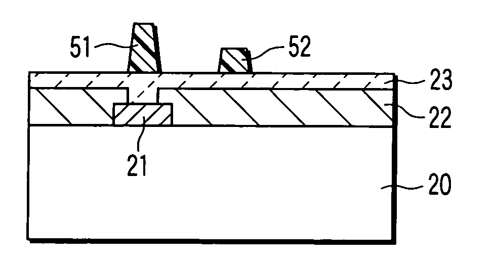
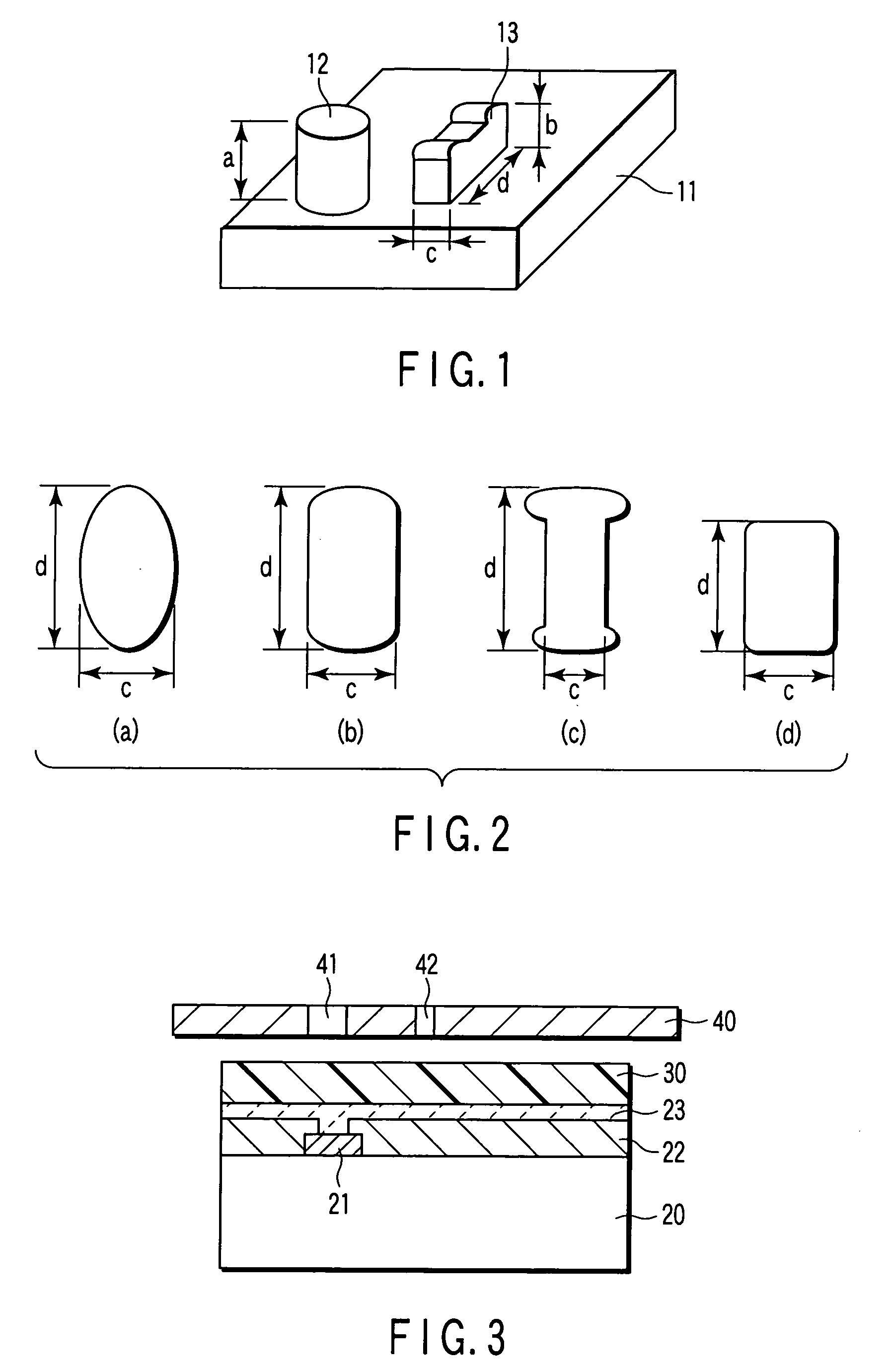
[0057]A method of manufacturing a color filter provided with main photo-spacers 12, 51 and subphoto-spacers 13, 52 as shown in FIGS. 1 and 5 will be explained with reference to FIG. 3.
[0058]As shown in FIG. 3, a photoresist layer 30 is formed on the surface of a glass substrate 20 having a black matrix 21, a color pixel 22 and a transparent conductive film 23 deposited successively thereon. Over this photoresist layer 30, there is disposed a photomask 40 for creating photo-spacers for color filter with a gap (G) for proximity exposure being interposed therebetween.
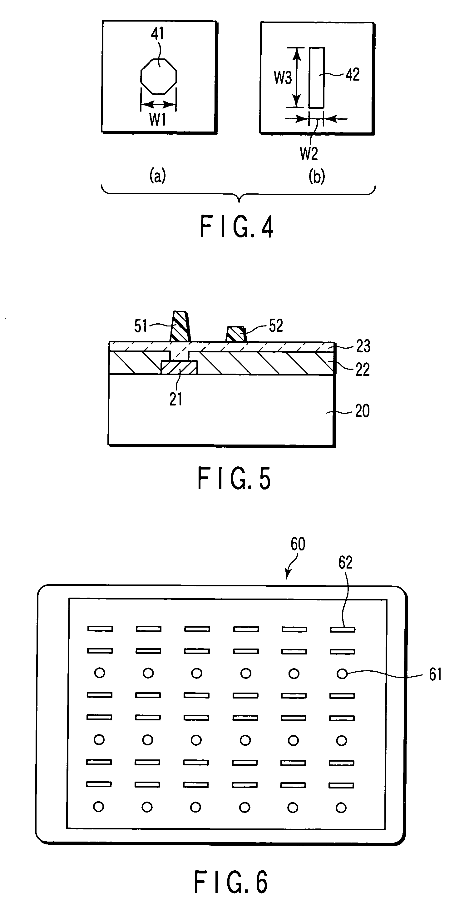
[0059]This photomask 40 is provided with apertures 41 and 42 corresponding to the main photo-spacer and the subphoto-spacer, respectively. One example of the configuration of aperture 41 is shown in FIG. 4(a) and one example of the configuration of aperture 42 is shown in FIG. 4(b). As shown in FIG. 4(a), the configuration of aperture 41 is octagonal and as shown in FIG. 4(b), the configuration of aperture 42 is rectangula...
example 2
[0070]Photo-spacers were created in the same manner as described in Example 1 by making use of a photomask wherein the width W1 of the aperture 41 for forming the main photo-spacer was set to 15 μm and the aperture 42 for forming the subphoto-spacer was set to 8.0 μm in lateral width W2 and 10 μm in longitudinal width W3 (i.e., lateral width W2:longitudinal width W3=1:1.25). The height “a” of the main photo-spacer 51 thus created was 4.60 μm and the height “b” of the subphoto-spacer 52 thus created was 4.12 μm, thus giving a difference in height of 0.48 μm between the main photo-spacer 51 and the subphoto-spacer 52.
example 3
[0071]Photo-spacers were created in the same manner as described in Example 1 by making use of a photomask wherein the width W1 of the aperture 41 for forming the main photo-spacer was set to 10 μm and the aperture 42 for forming the subphoto-spacer was set to 5.0 μm in lateral width W2 and 15.0 μm in longitudinal width W3 (i.e., lateral width W2:longitudinal width W3=1:1.3). The height “a” of the main photo-spacer 51 thus created was 4.654 μm and the height “b” of the subphoto-spacer 52 thus created was 4.496 μm, thus giving a difference in height of 0.16 μm between the main photo-spacer 51 and the subphoto-spacer 52.
PUM
| Property | Measurement | Unit |
|---|---|---|
| thickness | aaaaa | aaaaa |
| lateral width | aaaaa | aaaaa |
| lateral width | aaaaa | aaaaa |
Abstract
Description
Claims
Application Information
 - R&D Engineer
- R&D Manager
- IP Professional
- Industry Leading Data Capabilities
- Powerful AI technology
- Patent DNA Extraction
Browse by: Latest US Patents, China's latest patents, Technical Efficacy Thesaurus, Application Domain, Technology Topic, Popular Technical Reports.
© 2024 PatSnap. All rights reserved.Legal|Privacy policy|Modern Slavery Act Transparency Statement|Sitemap|About US| Contact US: help@patsnap.com