Light source device, image display apparatus, and monitor apparatus

a technology of image display and light source, which is applied in the direction of optical radiation measurement, semiconductor lasers, instruments, etc., can solve the problems of inconvenient operation, inconvenient use, and inability to control the brightness of the laser beam, so as to reduce the coherence of laser beams and suppress speckle nois

Active Publication Date: 2009-01-15
SEIKO EPSON CORP
View PDF23 Cites 58 Cited by
  • Summary
  • Abstract
  • Description
  • Claims
  • Application Information

AI Technical Summary

Benefits of technology

[0008]An advantage of some aspects of the invention is to provide a light source device, an image display apparatus, and a monitor apparatus in which coherence among plural laser beams is reduced and speckle noise is suppressed.

Problems solved by technology

However, such a discharge lamp has problems in that durable life is short, instantaneous lighting is difficult, a color reproducibility range is narrow, and an ultraviolet ray radiated from the lamp deteriorates a liquid crystal light valve.
The laser light source does not have the problems described above but is disadvantageous in that the laser light source has coherence.
Consequently, an interference fringe appears as speckle noise and an image is deteriorated on a projection surface on which a laser beam is projected.
Consequently, speckle patterns of the lights emitted from the respective light selection areas change complexly as time elapses.
Consequently, speckle patterns of the lights emitted from the light selection areas of the wavelength selection element complexly change as time elapses.

Method used


Image

  • Light source device, image display apparatus, and monitor apparatus
  • Light source device, image display apparatus, and monitor apparatus
  • Light source device, image display apparatus, and monitor apparatus

Examples


first embodiment

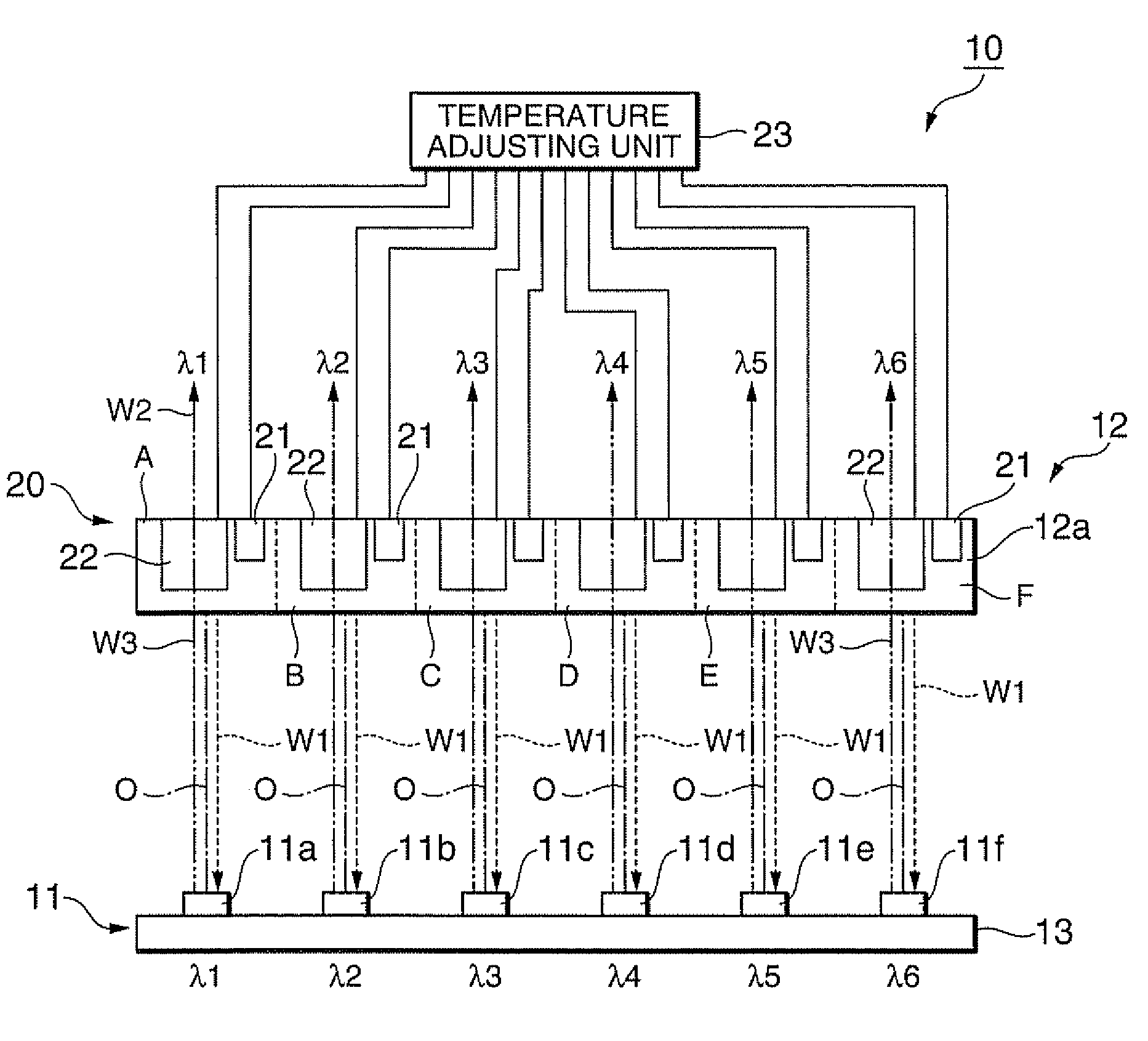
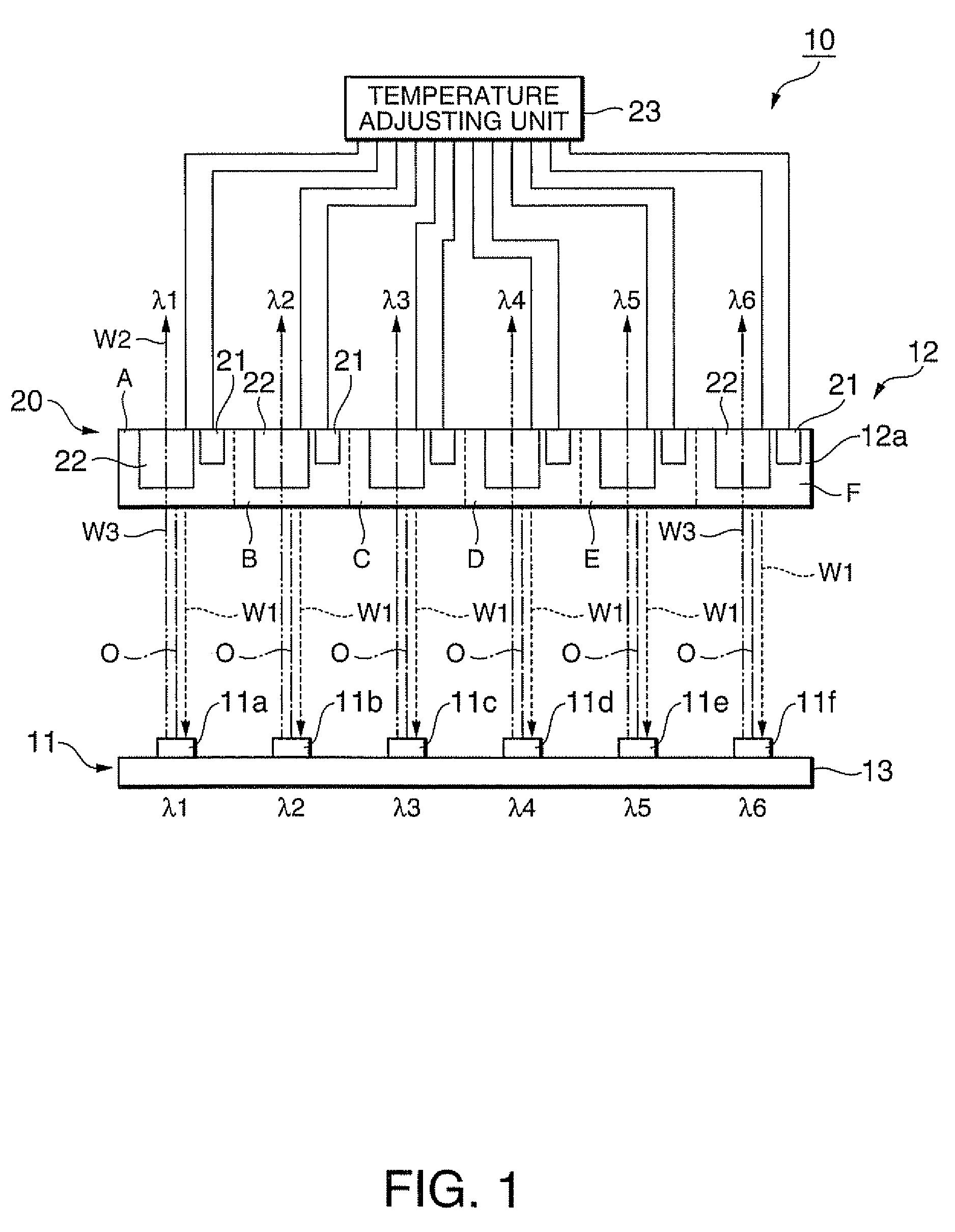
[0063]A first embodiment of the invention is explained with reference to FIG. 1.

[0064]As shown in FIG. 1, a light source device 10 according to this embodiment includes a light-emitting unit 11, a wavelength selection element 12, and a control unit 20.

[0065]The light-emitting unit 11 includes six light-emitting elements (semiconductor lasers; LDs) 11a, 11b, 11c, 11d, 11e, and 11f that emit laser beams. All of these light-emitting elements 11a to 11f are supported by a supporting unit 13. Peak wavelengths of lights emitted from the light-emitting elements 11a to 11f are different by about several nanometers because of manufacturing errors of the light-emitting elements 11a to 11f. When wavelengths of the lights emitted from the light-emitting elements 11a to 11f are represented as λ1, λ2, λ3, λ4, λ5, and λ6, the wavelengths have a relation λ1>λ4>λ5>λ3>λ2>λ6. Rather than the wavelengths are accidentally different because of the manufacturing errors, light-emitting elements that emit l...

second embodiment

[0103]A second embodiment according to the invention is explained with reference to FIG. 5. In the drawings in respective embodiments explained below, components same as those of the light source device 10 according to the first embodiment are denoted by the same reference numerals and signs and explanation of the components is omitted.

[0104]A light source device 40 according to this embodiment is different from the light source device 10 of the first embodiment in that the light source device 40 includes a light-intensity adjusting unit 45 that adjusts intensities of lights emitted from the areas A to F. Otherwise, the light source device 40 is the same as the light source device 10 according to the first embodiment.

[0105]As shown in FIG. 5, the light-intensity adjusting unit 45 includes light intensity sensors (light-intensity detecting unit) 41, mirrors 42, and a light-emitting-element control unit 43. In this embodiment, the light source device 40 includes the temperature adjust...

third embodiment

[0115]A third embodiment of the invention is explained with reference to FIG. 7.

[0116]As shown in FIG. 7, a light source device 50 according to this embodiment includes a light-emitting unit 51, a wavelength conversion element 53 that converts a waveform of light emitted from the light-emitting unit 51, and a wavelength selection element 52 that selects the wavelength converted by the wavelength conversion element 53 and reflects the light.

[0117]In FIG. 7, the temperature adjusting unit 23 on the wavelength selection element 52 side is not shown for simplification of the figure.

[0118]The light-emitting unit 51 includes six light-emitting elements (semiconductor lasers; LDs) 51, 51b, 51c, 51d, 51e, and 51f that emit laser beams. All of these light-emitting elements 51a to 51f are supported by a supporting unit 54. Peak wavelengths of lights emitted from the light-emitting elements 51a to 51f are different by about several nanometers because of manufacturing errors of the light-emitti...


PUM


Abstract

A light source device includes plural light-emitting elements that emit lights, a wavelength selection element that has plural light selection areas in which wavelength selection is performed for the lights emitted from the plural light-emitting elements, respectively, and selectively reflects a part of the lights emitted from the plural light-emitting elements, a state detecting unit that detects states of the plural light selection areas of the wavelength selection element, and a state changing unit that changes, according to the states of the plural light selection areas detected by the state detecting unit, the states of the light selection areas of the wavelength selection element to make wavelengths of the lights selected in the plural light selection areas different from one another.

Description

BACKGROUND[0001]1. Technical Field[0002]The present invention relates to a light source device, an image display apparatus, and a monitor apparatus.[0003]2. Related Art[0004]In projection type image display apparatuses in recent years, in general, a discharge lamp such as a super-high pressure mercury lamp is used as a light source. However, such a discharge lamp has problems in that durable life is short, instantaneous lighting is difficult, a color reproducibility range is narrow, and an ultraviolet ray radiated from the lamp deteriorates a liquid crystal light valve. Therefore, a projection type image display apparatus including a laser light source that irradiates monochromatic light is proposed instead of such a discharge lamp. The laser light source does not have the problems described above but is disadvantageous in that the laser light source has coherence. Consequently, an interference fringe appears as speckle noise and an image is deteriorated on a projection surface on w...

Claims


Application Information

Patent Timeline
Patent Type & Authority Applications(United States)
IPC IPC(8): H01S3/10
CPCG01J1/0252H01S5/4087G01J1/0414G01J1/0488G01J1/08G03B33/12H01S5/0687H01S5/4025H04N9/3105H04N9/3129H04N9/3161H04N9/3197G03B21/2013G03B21/2033G03B21/208H01S5/141G01J1/04
Inventor SUMIYAMA, FUMIKAMIYAMAE, AKIRA
Owner SEIKO EPSON CORP
Why Eureka
Try Eureka