Marine pier system

a pier system and marine technology, applied in the direction of piers, groynes, transportation and packaging, etc., can solve the problems of decking being a dangerous floating object, being subject to similar destructive reactions, and being exposed to the destructive forces of decking

Inactive Publication Date: 2009-01-15
BABER ROGER +1
View PDF20 Cites 1 Cited by
  • Summary
  • Abstract
  • Description
  • Claims
  • Application Information

AI Technical Summary

Benefits of technology

[0022]Still another objective of the invention is to address the problem with permits by eliminating the shading typically of conventional decking mounted on piers.

Problems solved by technology

The decking can consume a large surface area over the surface of the water, which exposes the decking to the destructive forces of weather, wind and waves.
Further should the water be rough due to high winds or large boat wakes, waves that strike the deck may result in a similar destructive reaction.
However, the break away decking can then become a dangerous floating object, as well as an expense and inconvenient to replace.
A large deck also creates an adverse environmental impact in many environmentally sensitive areas.
Thus, a properly designed dock has minimal spacing which has the detrimental effect of preventing sunlight from reaching the water.
Without sunlight, vegetation such as sea-grass cannot grow.
This has an adverse impact on the aquatic animal life and is currently heavily regulated in many states, the loss of sea-grass having a detrimental effect on all aspects of marine life.
Another problem with conventional piers is security since it allows easy access for unauthorized persons to approach marine craft moored thereto.
The pier cart operates as addition to a conventional pier and does not address wind, waves, security or the continuing harm caused by decking that shades the water.
Such prior art systems fail to teach or disclose a marine pier system which is not susceptible to destructive wind and wave action, or provide a pier which will improve the environment by allowing the growth of sea-grasses below a support structure.
Security of the marine craft moored to the pier or pier is a further issue the prior art fails to address.

Method used


Image

  • Marine pier system
  • Marine pier system
  • Marine pier system

Examples


Embodiment Construction

[0044]While the present invention is susceptible of embodiment in various forms, there is shown in the drawings and will hereinafter be described a presently preferred embodiment with the understanding that the present disclosure is to be considered an exemplification of the invention and is not intended to limit the invention to the specific embodiments illustrated.

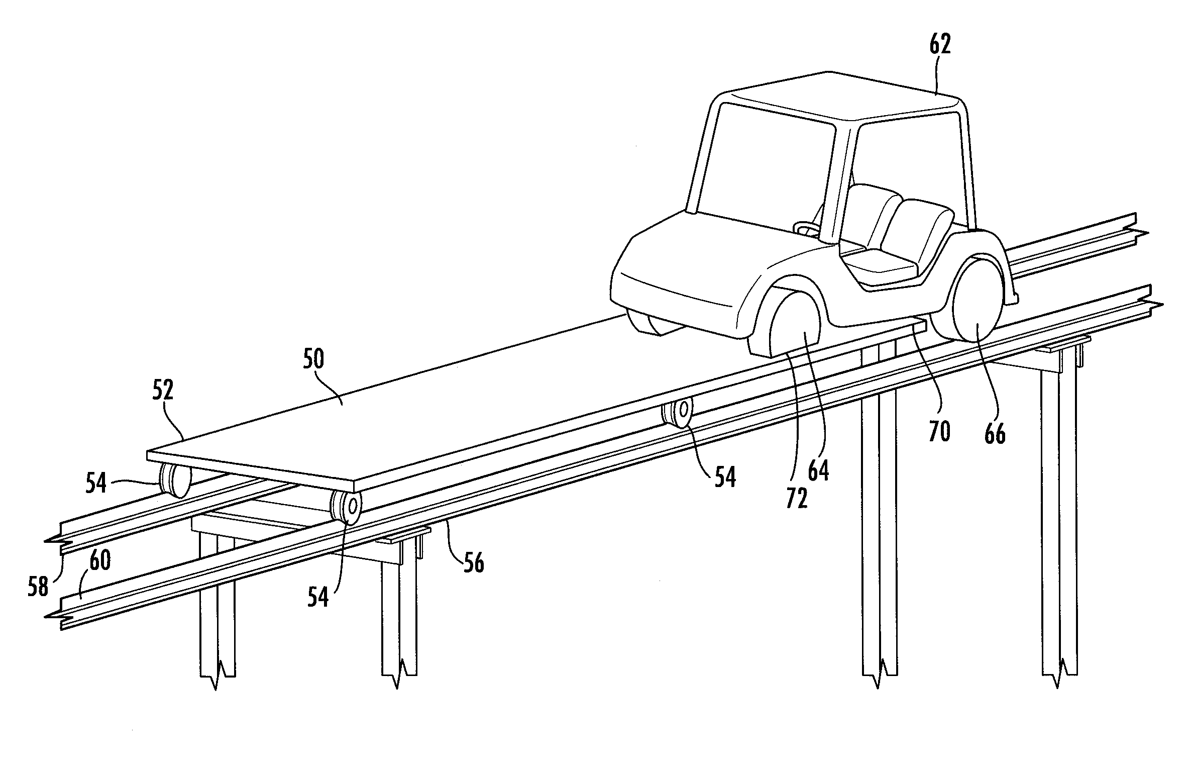
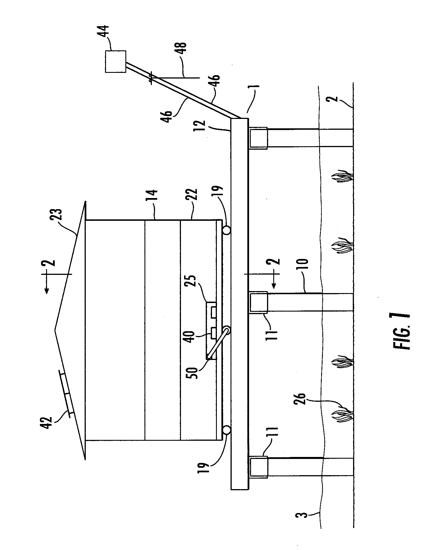
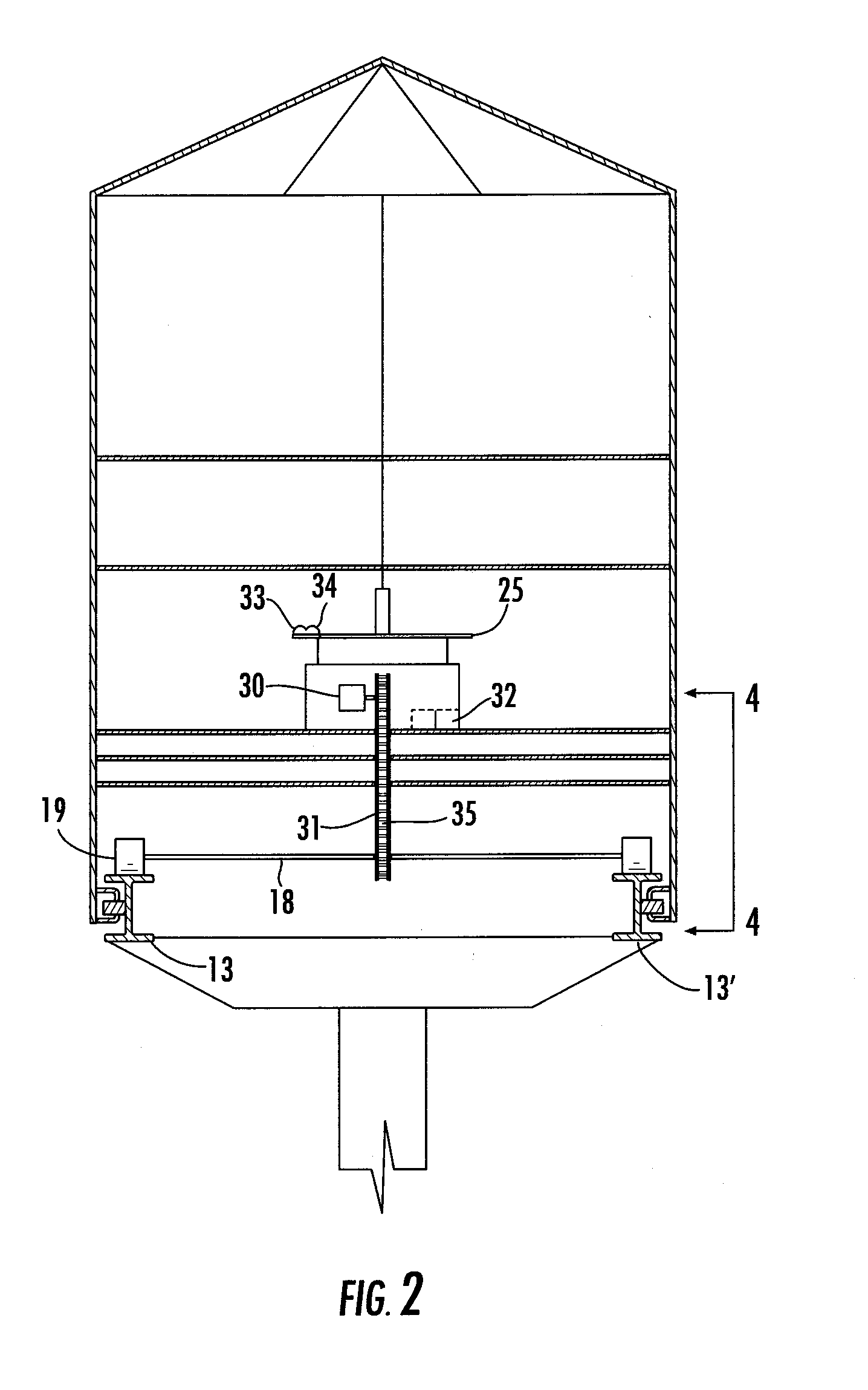
[0045]Referring generally to the Figures, the present invention is illustrated by use of a pier 1 having a payload transport device 14 to transport people and equipment along the pier. The transport device can assimilate conventional decking on a pier and further include side rails 17, seats 21 and a roof 23. However, the main difference is that the transport device is movable along a payload rail system 12 in which the preferred embodiment is a self-propelled carriage wherein a drive system 25, such as a battery powered electric motor 30.

[0046]The support system for the carrier is provided by a plurality of pilings 10 a...


PUM


Abstract

A marine pier system employing a payload transport device for transporting persons and material from land to marine craft moored at a distal end of the pier. The payload transport is a movable deck having either an electric motor powered by batteries for use in moving the deck and persons/material placed on the deck, or employs the use of a separate vehicle, such as a golf cart, for propulsion of the deck. The payload transport device may be self-contained eliminating the necessity for decking along the length of the pier. The absence of decking provides a structure upon which wind and wave action and deterioration from sunlight and weathering has little destructive effect, and further allows sunlight to reach the aquatic life below the surface of the water. The movable transport device further permits sunlight to reach all areas of sea grass that are shaded by movement of the transport device to a non-sensitive area when not in use.

Description

PRIORITY CLAIM[0001]This application is a continuation-in-part of U.S. patent application Ser. No. 11 / 195,059, filed Aug. 1, 2005, the contents of which are incorporated herein by reference.FIELD OF THE INVENTION[0002]The present invention relates to docking of marine craft and, more particularly, to a marine pier system having a carriage supported by a fixed track having a proximal end secured to dry land and mounted on pilings for extension over water. The carriage can be used to transport people, supplies, and any other items along the length of pier to access marine craft moored along a distal end of the marine pier. The carriage provides for a movable deck enabling the convenience of a conventional pier without the disadvantages.BACKGROUND INFORMATION[0003]Piers are used to provide access to sail boats, power boats, jet skis and the like marine craft. Piers, also referred to as “docks”, are available in a variety of configurations. The main objective of a pier is to provide a s...

Claims


Application Information

Patent Timeline
Patent Type & Authority Applications(United States)
IPC IPC(8): E02B3/06
CPCE02B3/068Y02A10/11
Inventor BABER, ROGERJERNER, BRUCE
Owner BABER ROGER
Why Eureka
Try Eureka