Secondary battery, power supply system using same and usage of power supply system

Inactive Publication Date: 2009-01-15
PANASONIC CORP
View PDF7 Cites 95 Cited by
  • Summary
  • Abstract
  • Description
  • Claims
  • Application Information

AI Technical Summary

Benefits of technology

[0010]The present invention provides a new type of secondary battery using an organic compound excellent in reversibility as an active material. No heavy metal is used so as to avoid the problem of environmental load. No radical is also used so as to avoid the deterioration of battery performance. Furthermore, the present invention relates to a power supply system using the secondary battery. The secondary battery is essentially composed of a positive electrode active material, a positive electrode current collector, a negative electrode active material, a negative electrode current collector and a separator. The positive electrode current collector oxidizes and reduces the positive electrode active material, and the negative electrode current collector oxidizes and reduces the negative electrode active material. The ion conductive separator separates at least between the positive electrode active material and the negative electrode active material. At least one of the positive electrode active material and the negative electrode active material is an o

Problems solved by technology

However, inorganic redox flow batteries using heavy metal ions have limitations in attaining high-capacity and high-power, due to the limitation of solubility of active materials in the electrolytic solution, the limitation of reaction potential due to the use of the aqueous electrolytic solutions, and the like.
In other words, the active material essentially includes a metal, and therefore the problem of environmental load cannot be dissolved.
Therefore, the

Method used


Image

  • Secondary battery, power supply system using same and usage of power supply system
  • Secondary battery, power supply system using same and usage of power supply system
  • Secondary battery, power supply system using same and usage of power supply system

Examples


first exemplary embodiment

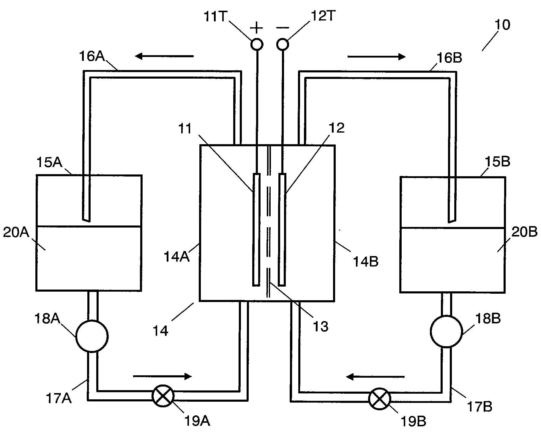
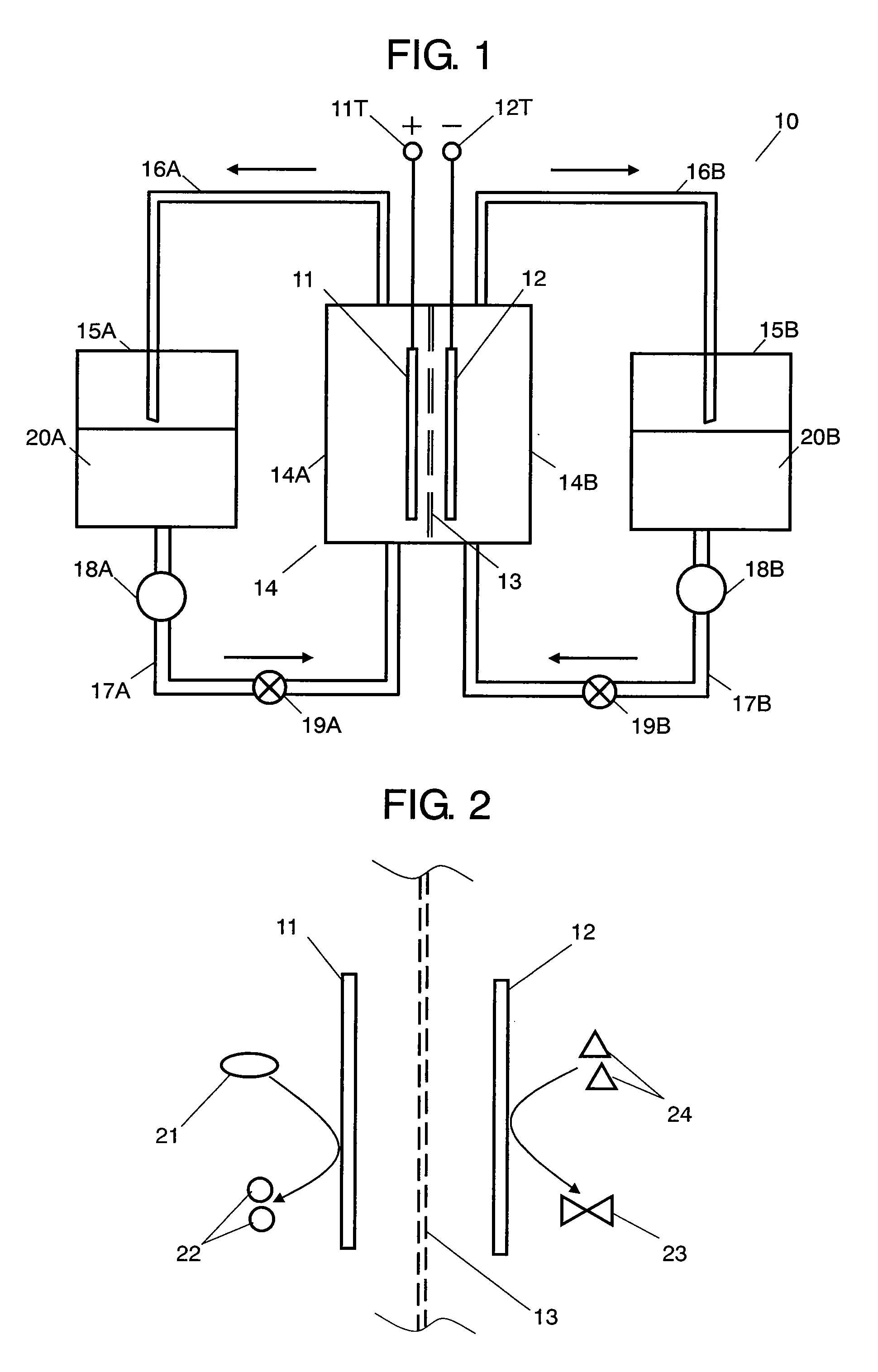
[0022]FIG. 1 is an outline view showing a configuration to illustrate the basic structure of a redox flow battery that is one kind of a secondary battery in accordance with the exemplary embodiment of the present invention. Positive electrode current collector 11 (hereinafter, referred to as current collector 11) contained in container 14 and oxidizing and reducing a positive electrode active material is coupled to positive electrode terminal 11T outside of container 14. Similarly, negative electrode current collector 12 (hereinafter, referred to as current collector 12) oxidizing and reducing a negative electrode active material is coupled to negative electrode terminal 12T. Container 14 is separated into positive electrode chamber 14A and negative electrode chamber 14B by separator 13. Current collector 11 is contained in positive electrode chamber 14A, and current collector 12 is contained in negative electrode chamber 14B.

[0023]Tank 15A contains positive electrode solution 20A i...

second exemplary embodiment

[0106]A power supply system applying the secondary battery described in the first exemplary embodiment is described. FIG. 4 is a conceptual diagram showing a power supply system combining a secondary battery in accordance with the first exemplary embodiment of the present invention and a fuel cell that is a power supply for supplying electric power to the secondary battery.

[0107]Positive electrode terminal 32 of fuel cell 31 is coupled to positive electrode terminal 11T of battery 10 and negative electrode terminal 33 is coupled to negative electrode terminal 12T, respectively, and both are coupled to load 34. That is to say, fuel cell 31 and battery 10 are coupled in parallel. Since battery 10 has a structure shown in FIG. 1, the description is omitted. Furthermore, although not shown, between battery 10 and fuel cell 31, a regulator for regulating the charging voltage is provided. Furthermore, it is preferable that a switch for selecting a circuit is provided in an arbitrary porti...

third exemplary embodiment

[0122]Next, another power supply system using the secondary battery described in the first exemplary embodiment is described. FIG. 7 is a conceptual diagram showing a power supply system that combines battery 10 and solar battery 41. Positive electrode terminal 42 of solar battery 41 is coupled to positive electrode terminal 11T of battery 10 and negative electrode terminal 43 is coupled to negative electrode terminal 12T, respectively, and both are coupled to load 34. Note here that since battery 10 has a structure shown in FIG. 1, the description thereof is omitted. Although not shown, between battery 10 and solar battery 41, a regulator for regulating the charging voltage is provided. Furthermore, it is preferable that a switch for selecting circuit is provided in arbitrary portions.

[0123]In this power supply system, battery 10 is constantly charged by solar battery 41. However, in general, an output from a solar battery varies depending upon the irradiation conditions of light i...


PUM


Abstract

A secondary battery is equipped with a reaction container and a current collector that is built in at least one of a positive electrode side and a negative electrode side. The positive electrode side and the negative electrode side are separated from each other by an ion conductive separator. In the reaction container, an organic matter excluding a metal complex and a radical and capable of reversibly being electrochemically oxidized and reduced is used as an active material together with a supporting salt. The active material and the supporting salt form a liquid. On the surface of the current collector, the active material contained in the liquid is charged and discharged.

Description

RELATED APPLICATIONS[0001]This application is the U.S. National Phase under 35 U.S.C. § 371 of International Application No. PCT / JP2006 / 310728, filed on May 30, 2006, which in turn claims the benefit of Japanese Application No. 2005-158701, filed on May 31, 2005, the disclosures of which Applications are incorporated by reference herein.TECHNICAL FIELD[0002]The present invention relates to a secondary battery having a liquid-state electrode including an organic compound as an active material and a power supply system using the same.BACKGROUND ART[0003]A secondary battery is a system for accumulating and releasing electric energy by charging and discharging. At present, secondary batteries have been widely used for, for example, a power supply of small-size portable devices, a mobile power supply for electric vehicles, a very large power supply for electric power or energy storage or for leveling the power output. In general, for secondary batteries, electrochemically oxidizable and ...

Claims


Application Information

Patent Timeline
IPC IPC(8): H01M4/60H01M10/44H01M10/05H01M10/36
CPCB60L11/1816Y02T90/127B60L11/1879B60L2210/30H01M4/60H01M8/18H01M8/20H01M10/05H01M10/44Y02E60/528Y02T10/7005Y02T10/7241Y02T10/7066Y02T90/14B60L11/1868B60L58/20B60L50/64Y02E60/50Y02T10/70Y02T10/72Y02E60/10Y02T10/7072Y02T90/12
Inventor INATOMI, YUUHOJO, NOBUHIKOKURANUKI, MASAAKI
Owner PANASONIC CORP
Why Eureka
Try Eureka