Combustion control system of detection and analysis of gas or fuel oil flames using optical devices

a combustion control system and optical device technology, applied in lighting and heating apparatus, instruments, heating types, etc., can solve the problems of difficult to have a line of view of only one radiation, radiation disables the use of such devices in a furnace with multiple burners, and detectors are very sensitive to changes in combustion, so as to optimize combustion process efficiency

Inactive Publication Date: 2009-01-15
UNIV DE CONCEPCION +2
View PDF65 Cites 35 Cited by
  • Summary
  • Abstract
  • Description
  • Claims
  • Application Information

AI Technical Summary

Problems solved by technology

Due to the produced optical phenomena and the lack of rigor in the construction of the electronics responsible for device handling, the results were unsatisfactory.
Furthermore, these channels are correlated to each other and certain procedures that require independence of the different color channels cannot be performed [Angulo, (2005)].
Its design is limited to applications in power stations that use pulverized coal and its application depends on operator criteria and does not allow total automatization for burner control.
In a large furnace, there are many burners and it is difficult to have a line of view of only one radiation, considering especially that the flame morphology depends on the fuel source as well as other factors.
For these reasons, although devices sensitive to radiation amplitude can work satisfactorily with a single burner, the high level of background radiation disables the use of such devices in a furnace with multiple burners.
Nevertheless, such detector is very sensitive to changes in combustion conditions that modify the distance along the flame axis in which the fuel ignites.
The use of the radiometer in the visible spectral radiation range could increase the costs.
This system has many measuring sub-systems requiring sophisticated data processing techniques, resulting in a very complex and expensive system.
As a result, this solution is not attractive for small-scale combustion systems.
Therefore, this strategy used would not be valid for gas and oil flames
This control system establishes a wide operation region (finished combustion) and does not allow identification of the ideal one.

Method used


Image

  • Combustion control system of detection and analysis of gas or fuel oil flames using optical devices
  • Combustion control system of detection and analysis of gas or fuel oil flames using optical devices
  • Combustion control system of detection and analysis of gas or fuel oil flames using optical devices

Examples


Embodiment Construction

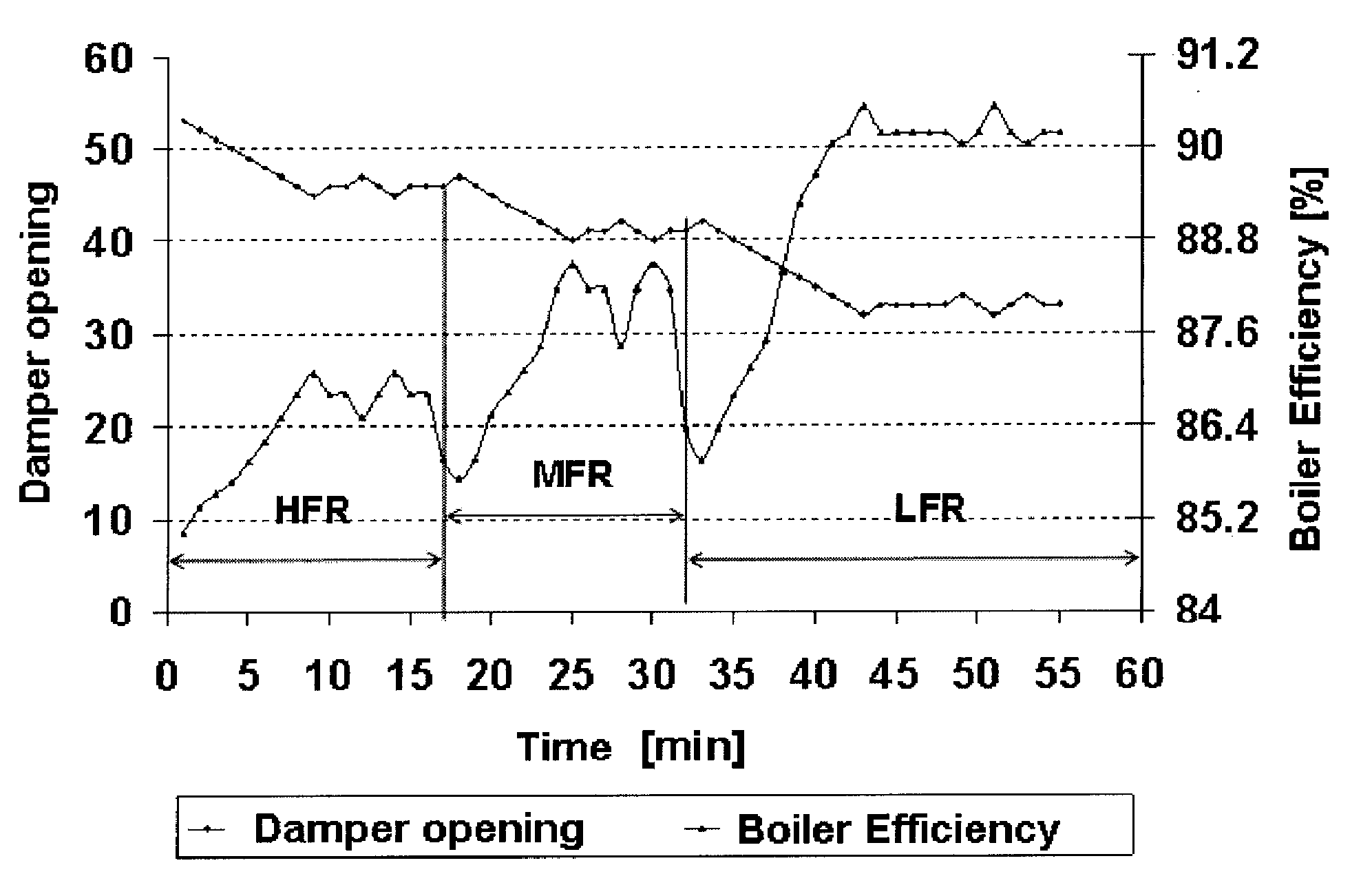
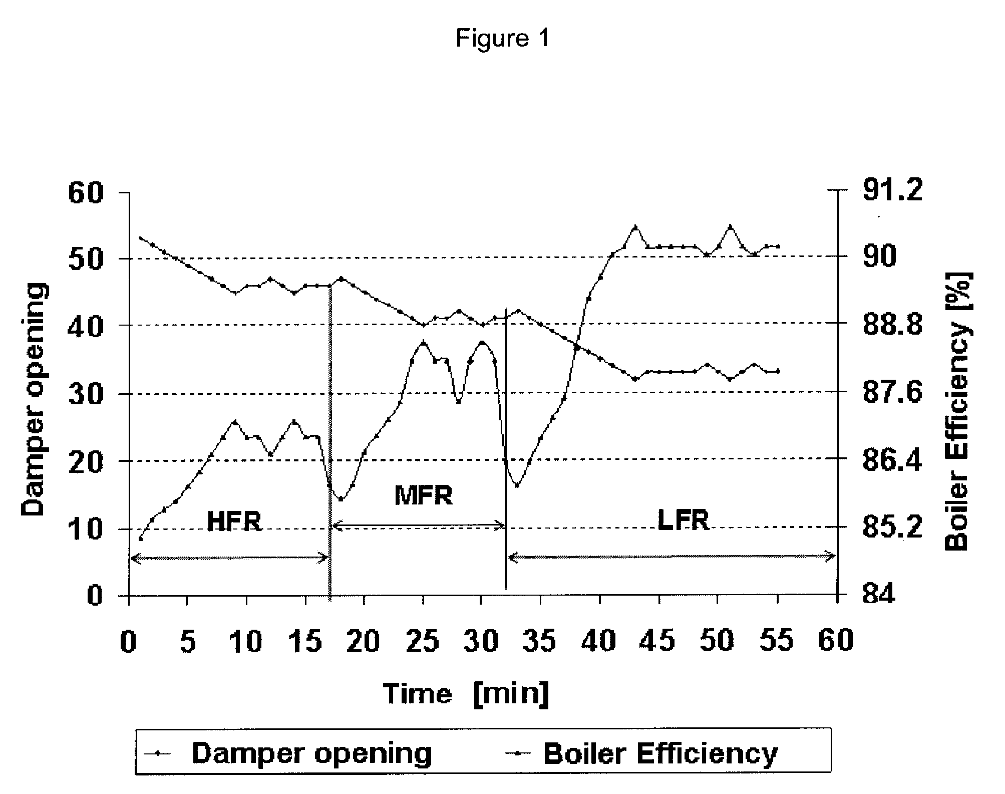
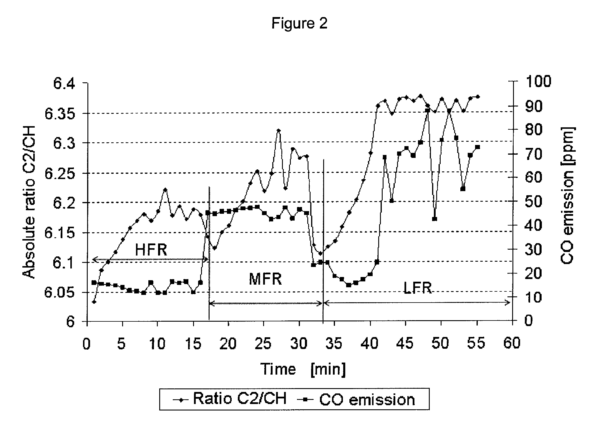
[0047]The invention consists of a system for flame detection and analysis typically of gas and fuel oil, using optical devices, typically photo detectors or cameras, located in the rear part of a furnace or in locations where they can target the flame reaction zone. The optical signals are transmitted to processing and control module, typically a computer system, that uses specific algorithms to process the optical signals, generating indicators to diagnose the combustion quality and to optimize equipment operation in terms of its efficiency and polluting emissions.

[0048]This flame detection and analysis system can be used as an autonomous system to diagnose industrial equipment or as part of a combustion control system in existing burners, boilers or industrial furnaces. In the second option, air control can be decoupled from the fuel control system, which is novel compared to traditional control schemes. For this reason, the system includes a control strategy that interacts with t...


PUM

PropertyMeasurementUnit
wave lengthsaaaaaaaaaa
timeaaaaaaaaaa

Abstract

A system of detection and analysis of gas or fuel oil flames using optical devices, consisting of a sensor that targets the flame's reaction zone through an optical access, a processing and control module, and an actuator, responsible for controlling the damper. The system optimizes combustion equipment operation by controlling the damper, obtaining better performance and reducing polluting emissions.

Description

FIELD OF THE INVENTION[0001]The present invention optimizes gas burner combustion using optical devices to analyze the flame. The optical signals are processed to diagnose the combustion state and optimize burner operations in terms of its efficiency and polluting emissions.BACKGROUND OF THE INVENTION[0002]Combustion research performed in the Combustion Laboratory has obtained important results based on the use of spectroscopy techniques and CCD imagining techniques. These results, obtained at laboratory level, have characterized different flame types according to the emission of free radicals and shooting particles [see Farias, Combustion Control in a Fuel Oil Boiler Frame the Flame Spectrum (1997) the disclosure of which is incorporated herein by reference.][0003]Citing Zuo (1992), Tartari & Ngendakumana, [A Photodiode for Combustion Control, (2003) the disclosure of which is incorporated herein by reference.] present the application of photo diodes to detect radicals at particula...

Claims


Application Information

Patent Timeline
Patent Type & Authority Applications(United States)
IPC IPC(8): F23N5/08G01N21/71
CPCF23N3/002F23N5/082G01N21/72
Inventor FARIAS FUENTES, OSCAR FRANCISCOHOFER, DANIEL GERONIMO SBARBAROASTETE, ROBINSON EUGENIO BETANCOURT
Owner UNIV DE CONCEPCION
Why Eureka
Try Eureka