
Chain tensioner

Active Publication Date: 2009-01-15
NTN CORP
View PDF6 Cites 19 Cited by
  • Summary
  • Abstract
  • Description
  • Claims
  • Application Information

AI Technical Summary

Benefits of technology

[0014]Since the opening of the retainer is formed by punching the retainer from inside to outside thereof, the ruptured surface is located radially outwardly of the shear surface. Thus, when the check ball collides against the bottom of the retainer, the ruptured surface is subjected to lower stress than the shear surface. This minimizes the possibility of formation of cracks in the ruptured surface due to stress concentration.
[0015]In the arrangement in which the retainer is made of steel and subjected to soft nitriding, carburizing / quenching or carbonitriding / quenching, the surface hardness of the retainer is high, so that the retainer is more durable.
[0016]By further subjecting the surface of this retainer to shot peening, residual compressive stress is produced on the surface of the retainer, so that the fatigue strength of the retainer further increases.
[0017]By carrying out the shot peening so as to raise the surface temperature of the retainer to the A3 transformation point or higher, the residual austenite on the surface of the retainer turns into martensite, and also, the surface structure of the retainer is recrystallized and becomes fine. This further increases the fatigue strength of the retainer.

Problems solved by technology

Since the ruptured surface 54 tends to be subjected to higher stress and is rougher than the shear surface 53, cracks tend to develop in the ruptured surface 54 due to stress concentration, which can result in fatigue failure of the retainer 51.

Method used


Image

  • Chain tensioner
  • Chain tensioner
  • Chain tensioner

Examples


example 1

[0051]A fatigue test was conducted on two sample retainers for a chain tensioner according to Example 1 of the invention and two sample retainers for a chain tensioner according to Comparative Example.

[0052]The retainers all have a wall thickness of 0.5 mm. In Example 1 of the invention, the opening is formed by punching each retainer from inside to outside as shown in FIGS. 3 and 4. In Comparative Example, the opening is formed by punching each retainer from outside to inside as shown in FIGS. 9 and 10.

[0053]Loads of 30 N was applied with a frequency of 200 Hz to the bottom of each of the two sample retainers according Example 1 of the invention and the two sample retainers of Comparative Example. The number of loads applied to each sample was measured when fatigue failure occurred at the border between the bottom and the tubular portion of the retainer. The measurement results are shown in FIG. 5.

[0054]As shown in FIG. 5, while the retainers of Comparative Example suffered fatigue...

example 2

[0056]A fatigue test was conducted on two sample retainers for a chain tensioner according to Example 2 of the invention and two sample retainers for a chain tensioner according to Reference Example.

[0057]The retainers are all made of steel and have the same wall thickness with the opening thereof formed by punching each retainer from inside to outside. Also, the retainers are all subjected to carbonitriding / quenching. The retainers according to Example 2 of the invention have their surfaces subjected to shot peening as shown in FIGS. 6 and 7. The retainers of Reference Example are not subjected to such shot peening.

[0058]The shot peening of the retainers according to Example 2 of the invention was carried out by throwing shots having diameters of 50 μm against the surface of each retainer at a speed of 50 m / minute. By this shot peening, the surface of each retainer is repeatedly and quickly cooled and heated within the temperature range higher than the A3 transformation point.

[0059...


PUM


Abstract

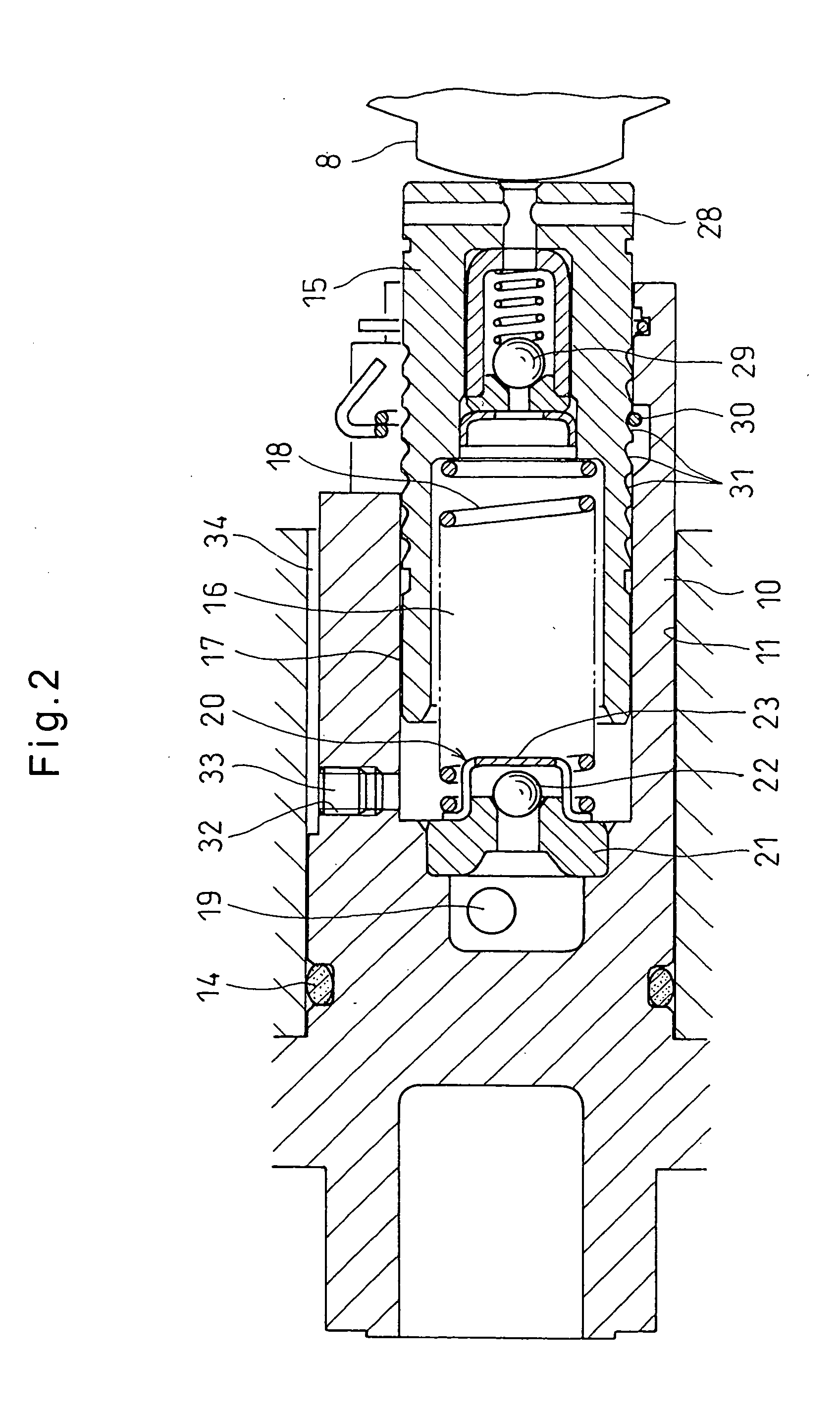
A chain tensioner includes a plunger axially slidably inserted in the cylinder for pressing a chain. The plunger defines in the cylinder a pressure chamber filled with hydraulic oil. The volume of the pressure chamber is variable with the axial movement of the plunger. The pressure chamber communicates with the outside of the cylinder through a restricted passage defined between sliding surfaces of the plunger and the cylinder. A spring biases the plunger in a direction to increase the volume of the pressure chamber. The cylinder is formed with an oil supply passage through which the pressure chamber communicates with the outside of the cylinder. The chain tensioner further includes a check valve which allows only a flow of hydraulic oil through the oil supply passage from the outside of the cylinder to the pressure chamber. The check valve includes an annular valve seat, a check ball which is movable into and out of contact with the valve seat, and a retainer formed by drawing and retaining the check ball. The retainer includes a tubular portion and a bottom at one end of the tubular portion. The tubular portion of the retainer is formed with an opening through which hydraulic oil can flow into and out of the retainer. The opening extends to a border between the tubular portion and the bottom of the retainer and is formed by punching the tubular portion from inside to outside thereof.

Description

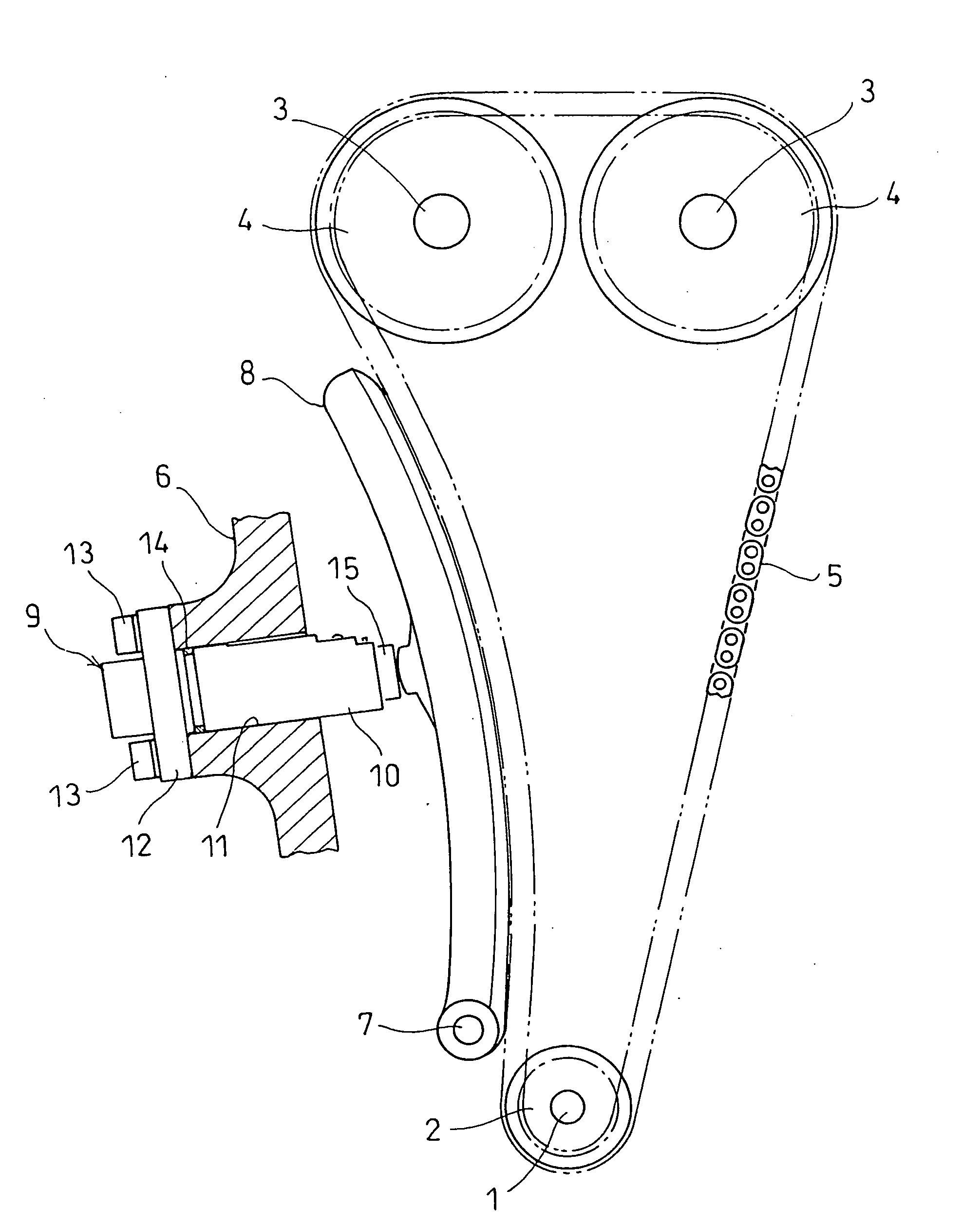
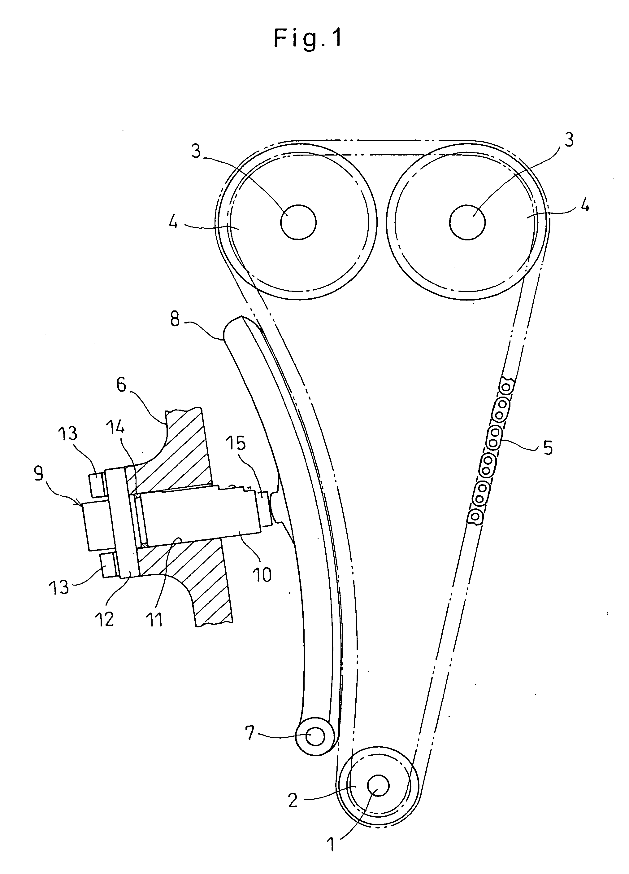
BACKGROUND OF THE INVENTION[0001]This invention relates to a chain tensioner for keeping constant the tension of a timing chain for driving camshafts in an automotive engine.[0002]In an automotive engine, the rotation of the crankshaft is transmitted to camshafts through a timing chain to rotate the camshafts, thereby repeatedly opening and closing valves of combustion chambers. In such an engine, in order to keep the tension of the chain within a proper range, a tension adjusting device is frequently used which comprises a chain guide pivotable about a shaft, and a chain tensioner biasing the chain guide in the direction to press the chain guide against the chain.[0003]Such chain tensioners typically comprise a cylinder having a closed end, a plunger axially slidably inserted in the cylinder for pressing a chain. The plunger defines in the cylinder a pressure chamber filled with hydraulic oil. The volume of the pressure chamber is variable with the axial movement of the plunger. Th...

Claims


Application Information

Patent Timeline
IPC IPC(8): F16H7/08
CPCF16H7/0836F16H2007/0806F16H2007/0878F16H2007/0859F16H2007/0812
Inventor SATO, TAKANOBUSATO, SEIJIONIMARU, KOUICHI
Owner NTN CORP
Features
  • Generate Ideas
  • Intellectual Property
  • Life Sciences
  • Materials
  • Tech Scout
  • Unparalleled Data Quality
  • Higher Quality Content
  • 60% Fewer Hallucinations
Learn More