Power cutter

a power cutter and cutter body technology, applied in the direction of propulsion parts, machines/engines, combustion air/fuel air treatment, etc., can solve the problems of only being able to draw air from the immediate vicinity of the carburetor, the amount of dust generated during the operation of the power cutter, and the engine speed to accelerate, etc., to achieve the effect of easy cleaning

Inactive Publication Date: 2009-01-22
BLACK & DECKER INC
View PDF59 Cites 33 Cited by
  • Summary
  • Abstract
  • Description
  • Claims
  • Application Information

AI Technical Summary

Benefits of technology

[0007]The present invention is intended to provide a

Problems solved by technology

Depression of the trigger switch causes more of the aerated petrol/oil mixture to be injected into the engine from the carburetor which in turn causes the speed of the engine to accelerate.
One problem associated with power cutters is the amount of dust generated during the operation of the power cutter and which surrounds the power cutter.
However, the carburetor is only able to draw air f

Method used


Image

  • Power cutter
  • Power cutter
  • Power cutter

Examples


second embodiment

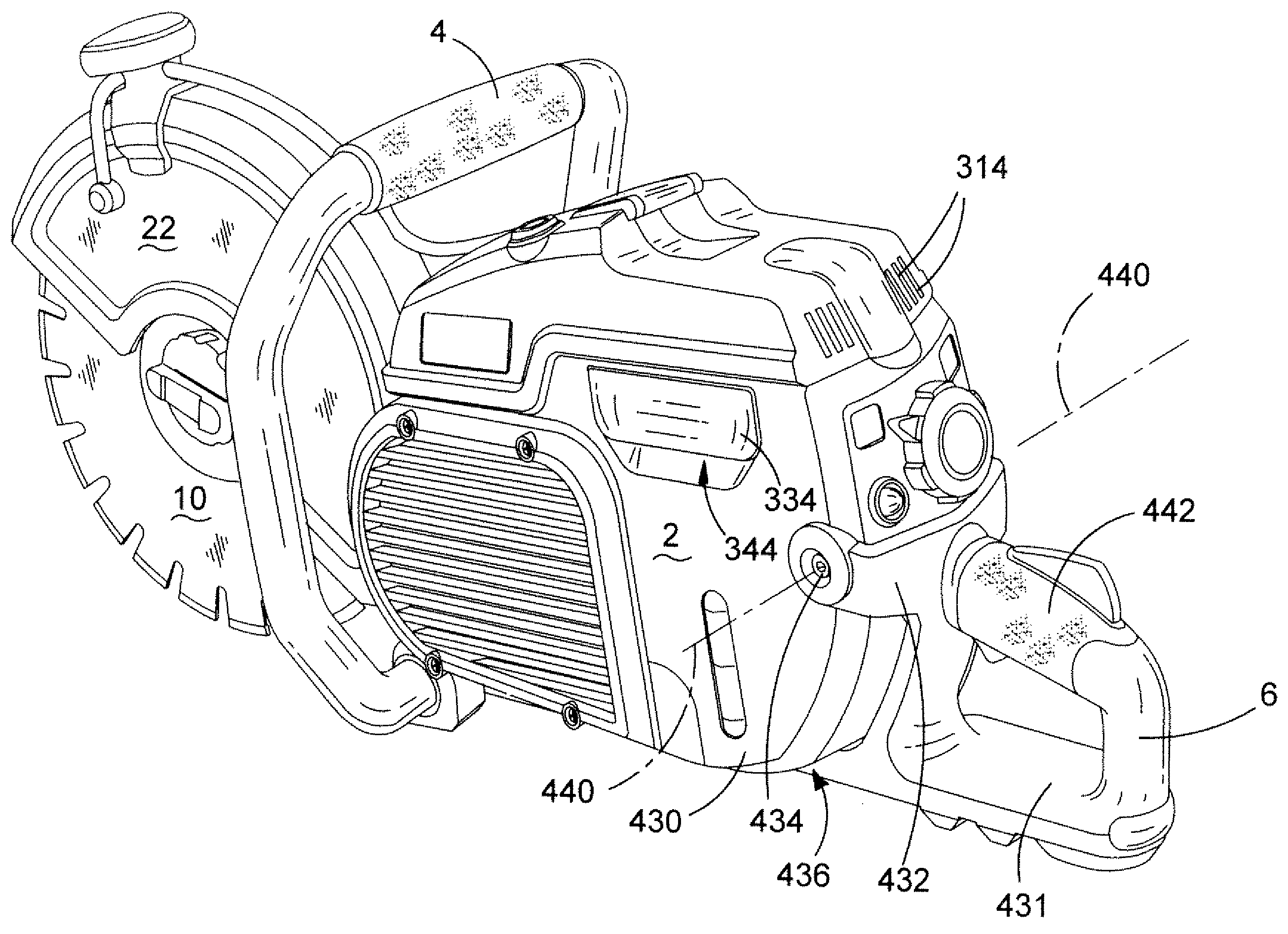
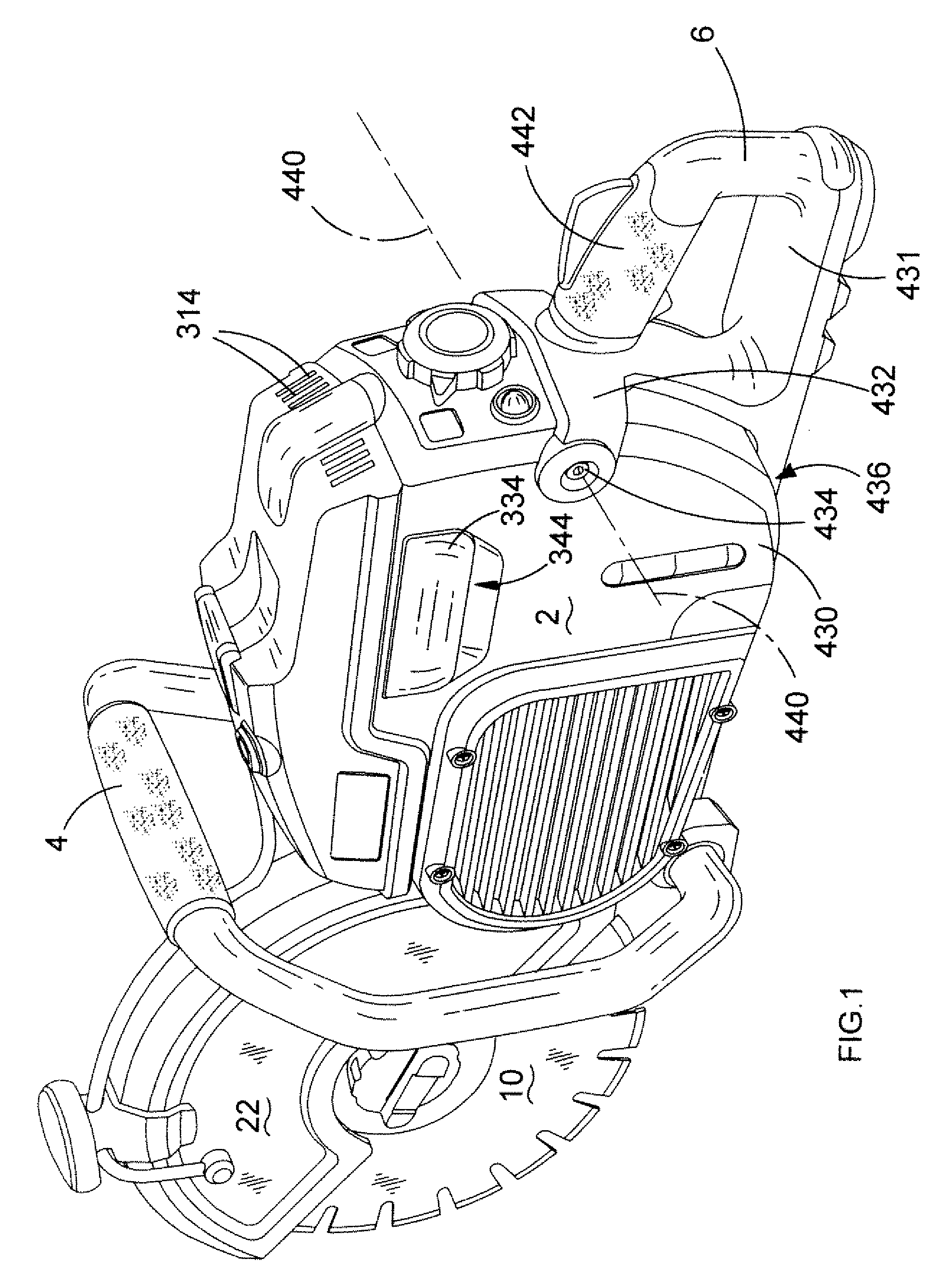
[0187]an air filtration system will now be described with reference to FIG. 30.

[0188]The filter device comprises a box 400 in which is mounted filter paper 402 which is pleated and which hangs down from the top section from inside the box. A space 404 is formed below the pleat. A large aperture 406 is formed in the side of the box below the filter paper and through which a drawer 408 can be slid. The drawer comprises a receptacle 410 which locates in the space 404 immediately below the filter paper 402. The drawer 408 can be fastened into place via a screw 412 which threadedly engages a threaded hole 414 in the box. Air passes through slots 314 into the box and into the receptacle 410 in the space 404 below the filter paper 402 then through the filter paper 402 into a space 416 above the filter paper 402 and then exits the space 416 above the filter paper through a flexible tube 418 to the carburetor 126. Any dust contained in the air entering the box 400 is blocked by the fitter pa...

first embodiment

[0190]The first system is very similar to that disclosed in the first embodiment described above and comprises a rubber flap 420 which is attached to the front end of the drawer 408. As the drawer 408 is inserted into the box 400 the rubber flap 420 engages with the pleated filter paper 402. As the drawer 408 slides into the box 400 the rubber flap 420 successively hits the base of each pleat causing any dust on the pleats to be knocked off and into the drawer 408. As such the action of inserting or removing the drawer 408 into the box 400 causes dust on the filter paper 402 to be loosened and allowed to be removed.

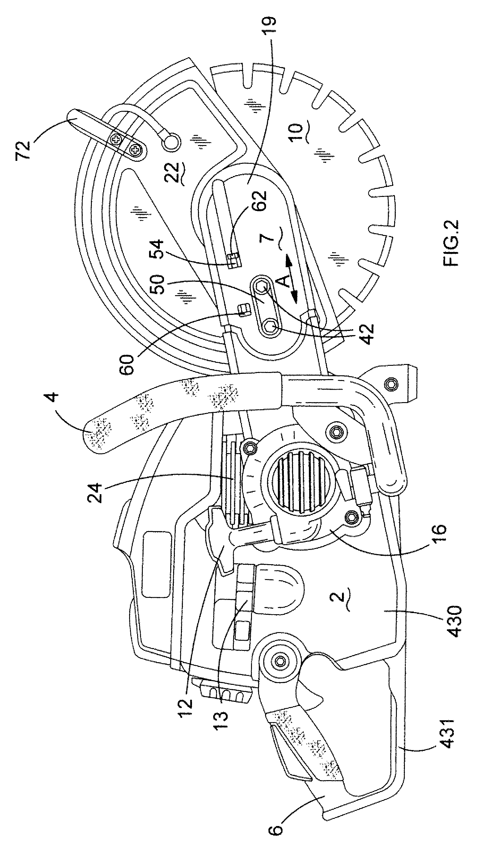
[0191]The second system relies on the starter cord 422 of the starter 12 for the two stroke engine 24 of the power saw. When the engine is started, the power cord 422 needs to be pulled in order to cause it to rotate. As the cord 422 is pulled, it rotates a pulley wheel 424 which causes an eccentric pin 426 to rotate about the axis 428 of the pulley 420. This causes one s...

fourth embodiment

[0195]FIGS. 33 to 47 show an air filtration mechanism of the invention.

[0196]The air filtration mechanism 600 of the power cuter of FIGS. 33 to 47 is connected by means of a flexible tube 602 to a carburetor 604. The power cutter has an outer housing 606 to which the air filtration mechanism 600 is mounted. The air filtration mechanism 600 has a filter housing 608 containing an air filter 610 (FIGS. 44 and 45) and is sealed by means of a cover 612. A clean air outlet of the filter housing 608 is connected by means of a circip 614 to the flexible tube 602 which is connected to an inlet of the carburetor 604, which is located underneath the filter housing 608 when the power cutter is in its standard orientation. This enables the air filtration mechanism 600 to be made of compact construction. A filter cleaning mechanism 616 (FIG. 35) is slidably attached to the filter housing 608 and is attached to a handle 618 (FIG. 34) mounted to the outer housing 606. A first opening 620 and a seco...


PUM

PropertyMeasurementUnit
Timeaaaaaaaaaa
Shapeaaaaaaaaaa
Gravityaaaaaaaaaa

Abstract

A power cutter comprising: a housing 2; an engine 24 mounted within the housing 2; a support arm 7 mounted on the housing and which projects forward of the housing; a blade mounting mechanism 70,90, 86, 92 rotatably mounted on the end of the support arm and which is capable of being rotationally driven by the engine 24 when the engine is running; a liquid fuel aeration mechanism 126 to generate aerated fuel for the engine; an air intake 314 for the provision of air for the liquid fuel aeration device 126; an air filtration mechanism 316 to filter the air drawn in from the air intake for the liquid fuel aeration mechanism; a fuel tank 124 for providing fuel to the liquid fuel aeration mechanism; and an exhaust 146 through which the exhaust gases generated by the operation of the engine are expelled; wherein the air filtration mechanism comprises an air filter 320 comprising a plurality of pleats and wherein the air filtration mechanism further comprises an air filter cleaning mechanism comprising a moveable pleat stroker 328; 342; 420 located adjacent the air filter 320 and which is capable of being moved over the pleats of the air filter 320, and which, when moved over the pleats, engages with the pleats and causes the pleats to flex in order to knock any dust trapped on the pleats, off the pleats.

Description

FIELD OF THE INVENTION[0001]The present invention relates to a power cutter.BACKGROUND OF THE INVENTION[0002]A typical power cutter comprises a housing in which is mounted a two stroke internal combustion engine. Attached to the side of the housing is a support arm which extends forward of the housing. Rotatably mounted on the end of the support arm is a cuffing blade, usually in the form of a grinding disk. The motor is drivingly connected to the cuffing blade via a drive belt. The rotary output of the engine rotatingly drives the cutting blade via the drive belt. The drive belt is driven via a centrifugal clutch which enables the out drive spindle of the engine to disengage from the belt when the engine is running at a slow speed, to allow the engine to continue running, whilst disengaging any drive to the cutting blade to allow the blade to be stationary.[0003]Also mounted in the housing is a petrol tank which provides petrol for the engine and an oil tank, which provides lubrica...

Claims


Application Information

Patent Timeline
IPC IPC(8): B27B9/00B01D46/42
CPCB01D46/0075B01D46/521B24B27/08B28D7/02F02M35/08F02M35/0203F02M35/024F02M35/06F01P11/06B01D46/76B23D45/16B27B5/32B60K15/0406F02B63/02F01M1/22B01D46/681
Inventor GROSSMAN, HORSTSELL, STEFANSOIKA, MARTIN
Owner BLACK & DECKER INC
Why Eureka
Try Eureka