Method of modular pole construction and modular pole assembly

a technology of modular poles and pole assemblies, which is applied in the direction of manufacturing tools, building repairs, transportation and packaging, etc., can solve the problems of not addressing other structural issues such as height, strength, stiffness, durability and other performance considerations, and achieves the effect of convenient storage and transportation and easy access to the structural properties of the modules

Active Publication Date: 2009-01-22
R&S TECH INC
View PDF66 Cites 36 Cited by
  • Summary
  • Abstract
  • Description
  • Claims
  • Application Information

AI Technical Summary

Benefits of technology

[0012]The present invention pertains to a method of modular pole construction as just defined, wherein after the step of stacking, there is a further step of positioning a cap at one or both ends of the elongated modular pole structure, thereby inhibiting entry of debris or moisture into the pole.
[0018]The present invention pertains to an elongated modular pole structure as just defined including a cap positioned at one or both ends of the extended modular pole structure, thereby inhibiting entry of debris or moisture into the pole structure.
[0025]The present invention pertains to an elongated composite modular pole structure as just defined including a cap positioned at one or both ends of the extended modular pole structure, thereby inhibiting entry of debris or moisture into the pole structure.
[0030]The present invention pertains to an elongated modular pole structure comprising at least a first and second hollow tapered module, each module having a first end and an opposed second end, a cross-section of the second end being less than a cross-section of the first end, wherein the second end of the first module is mated with the first end of the second module and the first module has a greater internal dimension than the external dimension of the second module, such that at least a portion of the second module can nest within the first module for ease of transport of the modules. The whole of the second module may nest within the first module and the first module may have a greater compressive strength than the second module.
[0041]By using hollow modules that are tapered so that one end of each module has a larger cross sectional area than the other end of the module, allows an elongate modular pole structure to be assembled by stacking modules whereby the larger end of one module mates with the smaller end of a second module. The modules may be specifically engineered with different structural properties so that modules can be selectively combined to provide poles having a number of different structural property combinations, thus providing a modular solution to the problem of having to satisfy varying performance criteria, without requiring a separate pole or structure for each condition.
[0042]By providing modules that may be shaped so that they can nest one within the other, allows for easy storage and transportation of the modules required for assembly of an elongate modular pole structure. Furthermore, by using modules made of composite material, especially filament wound polyurethane composite material, the elongate modular pole structure is light, strong and durable and the structural properties of the modules can be easily varied by changing the type, amount or make up of the reinforcement and / or resin component of the composite material.

Problems solved by technology

Whilst the use of these pole structures is extensive, it is limited as they tend to be one piece structures, therefore the height, strength and other properties are fixed.
However, whilst this approach may aid the transportation and erection, this does not address other issues within the structure such as height, strength, stiffness, durability and other performance considerations.

Method used


Image

  • Method of modular pole construction and modular pole assembly
  • Method of modular pole construction and modular pole assembly
  • Method of modular pole construction and modular pole assembly

Examples


Embodiment Construction

[0053]The following description is of a preferred embodiment.

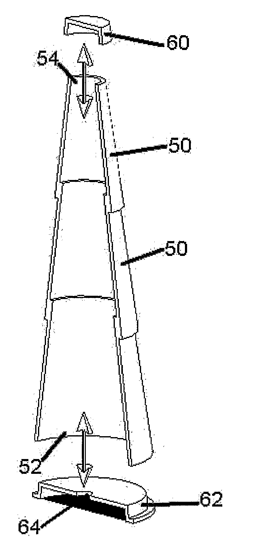
[0054]The present invention pertains to an elongated modular pole structure or modular pole assembly or system comprising two or more than two hollow tapered modules. Each module has a first end and an opposed second end with the cross-sectional area of the second end being less than the cross-sectional area of the first end. The second end of one module is mated with the first end of a second module to form the pole structure.

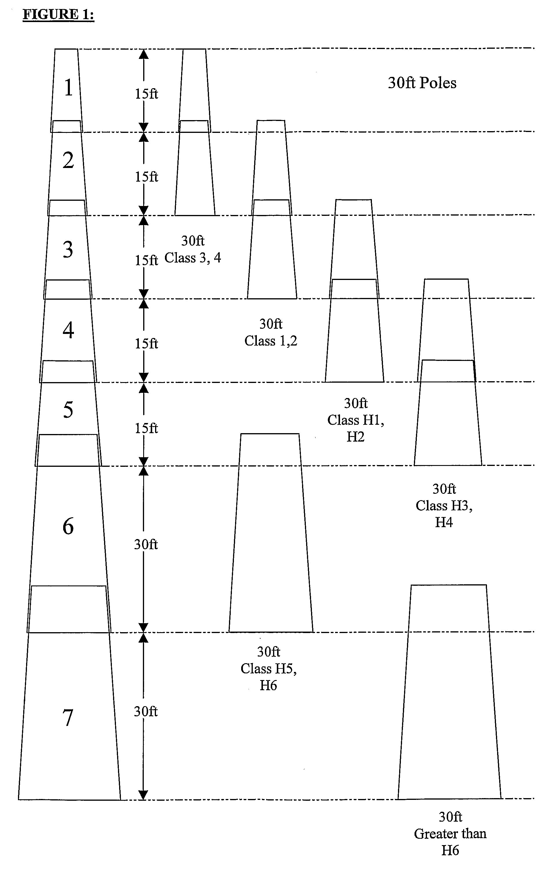
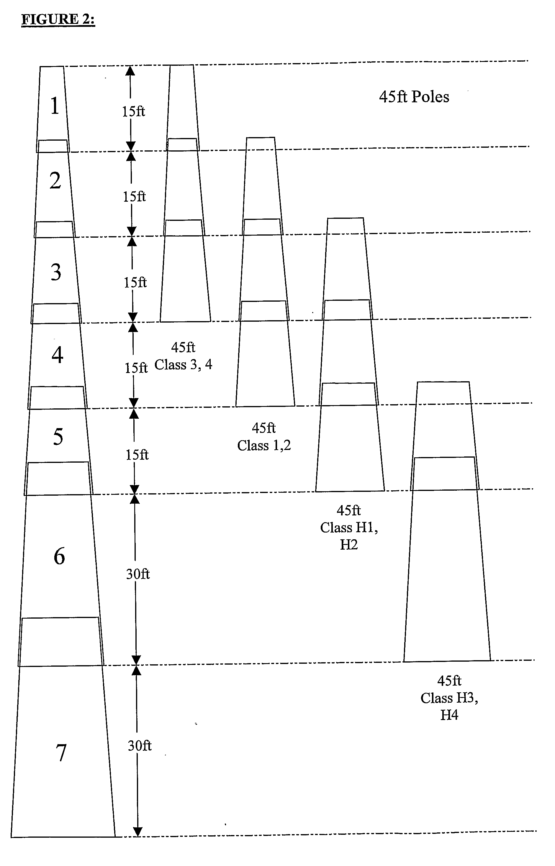
[0055]At least two of the modules may have different structural properties, such that poles having desired structural properties can be constructed by selectively combining modules having differing structural properties. The modules may have different flexural strength, compressive strength, resistance to buckling, shear strength, outer shell durability or a mixture of different structural properties. The height of the structure can also be varied simply by adding or removing modules from the stack. ...


PUM

PropertyMeasurementUnit
lengthsaaaaaaaaaa
anglesaaaaaaaaaa
anglesaaaaaaaaaa

Abstract

A method of modular pole construction an elongate modular pole structure is disclosed. A first step of the method involves providing hollow tapered pole section modules, each module having a first open end and an opposed second open end. A cross-section of the second end is less than a cross-section of the first end. The modules are stacked to form an elongated modular pole structure of a selected length by mating the second end of a first module with the first end of a second module. The first and second modules may have different structural properties, such that poles having desired structural properties can be constructed by selectively combining modules having differing structural properties.

Description

FIELD OF INVENTION[0001]The present invention relates to a method of modular pole construction and a modular pole assembly constructed in accordance with the teachings of the method.BACKGROUND OF THE INVENTION[0002]Pole structures are used for a variety of purposes, such as, but not limited to highway luminaire supports and utility poles for telephone, cable and electricity. These pole structures are typically made from materials such as wood, steel and concrete. Whilst the use of these pole structures is extensive, it is limited as they tend to be one piece structures, therefore the height, strength and other properties are fixed.[0003]Poles of a given length can be designed in multiple sections for ease of transporting by truck, railroad, or even cargo plane and to aid erection in the field. This is common with steel and indeed some concrete pole structures. U.S. Pat. No. 6,399,881 discloses a multi-sectional utility pole including at least two sections of straight pipe, which are...

Claims


Application Information

Patent Timeline
Patent Type & Authority Applications(United States)
IPC IPC(8): E04H12/18E04H12/00E04H12/34E04H12/02B31C99/00
CPCE04H12/02E04H12/08Y10T29/49826Y10T428/1393E04H12/34E04H12/18E04H12/342
Inventor LOCKWOOD, PHILCHAMBERS, DAVID
Owner R&S TECH INC
Why Eureka
Try Eureka