Method and Apparatus for a Cold Flow Subsea Hydrocarbon Production System

a hydrocarbon production system and cold flow technology, applied in the field of subsea methods and equipment, can solve the problems of increasing the cost of nearby deepwater offshore structures or hosts to support exploration and production, increasing the cost of local deepwater offshore structures or hosts, and reducing the throughput of pipelines and well production

Inactive Publication Date: 2009-01-22
SHELL OIL CO
View PDF57 Cites 37 Cited by
  • Summary
  • Abstract
  • Description
  • Claims
  • Application Information

AI Technical Summary

Problems solved by technology

Hydrocarbon production in a subsea environment is a capital intensive, time-consuming and challenging process.
The cost of nearby deepwater offshore structures or hosts to support exploration and production has become increasingly prohibitive, particularly in deep water (in excess of 3000 feet).
As the solids precipitate and solid hydrates form, they can, over time reduce the throughput of the pipeline and the production from the well.
To date, there have been no successful field implementations of these techniques.
However, these systems only attempt to ameliorate the effects of subsea cold and operating pressure.
Over large distances, even insulated pipe may not be effective in preventing deposition and pipeline clogging.
These systems can be effective but require significantly more expensive pipeline and heat support systems.
For extremely long transport distances, the costs associated with these types of systems may be prohibitive.
As such, chemical flow assurance, while effective, remains an expensive way to deal with the problem.
However, they also have some drawbacks.
When being deployed in long subsea runs, the material scraped off the inside of the pipeline wall typically tends to form an agglomerated slug, requiring increasing pressure to push the pig through the flow line, further decreasing production.

Method used


Image

  • Method and Apparatus for a Cold Flow Subsea Hydrocarbon Production System
  • Method and Apparatus for a Cold Flow Subsea Hydrocarbon Production System
  • Method and Apparatus for a Cold Flow Subsea Hydrocarbon Production System

Examples


example

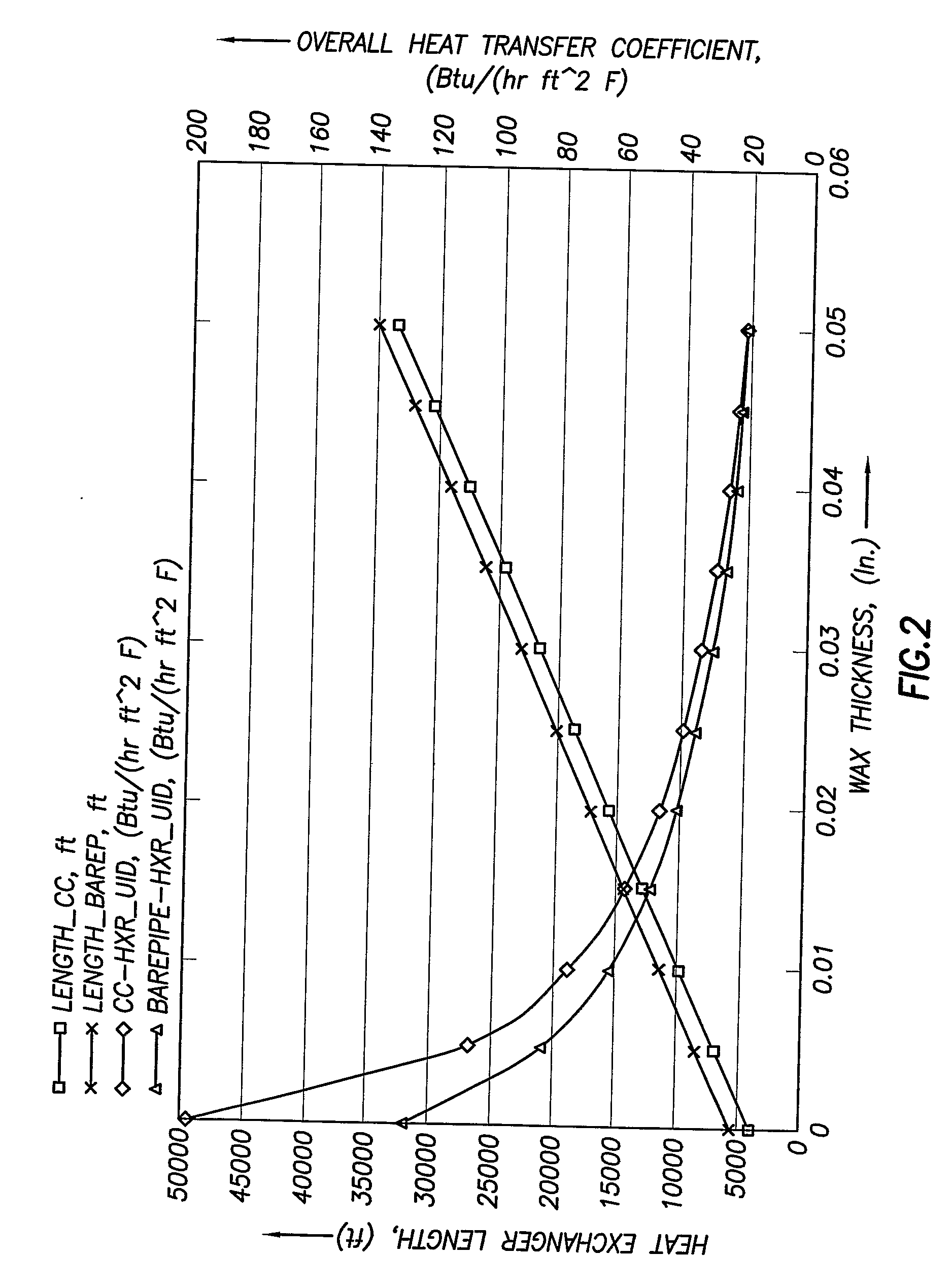
[0062]Exemplary calculations have been performed utilizing typical base-case conditions for a known reservoir producing 60,000 BPD with zero water cut, including its oil pressure, volume, temperature (PVT) properties, inlet pressure and temperature of 4000 psig and 150° F., an exchanger ID and OD of 7.001″ and 8.625″, a jacket pipe OD of 9.75″ and a wax thermal conductivity of 0.1 Btu / (hr ft F). FIGS. 2-4 show the predicted heat exchanger lengths for both exchanger options (i.e. countercurrent flow of seawater and direct convection due to seawater currents). The countercurrent heat exchanger has a significant advantage over the bare-pipe option only for very low (near zero) sea-water currents. For water currents of the order of 2 ft / s (customary in the Gulf of Mexico) there is not much difference between the two heat exchanger options. For a maximum deposit thickness of 0.01 inches, the required length of either heat exchanger type is ˜10,000 ft. Due to partial self-burial of a pipe...


PUM

PropertyMeasurementUnit
temperatureaaaaaaaaaa
temperaturesaaaaaaaaaa
temperatureaaaaaaaaaa

Abstract

A system for assuring subsea hydrocarbon production flow in pipelines by chilling the hydrocarbon production flow in a heat exchanger and causing solids to form, periodically removing deposits and placing them in a slurry utilizing a closed loop pig launching and receiving systems.

Description

FIELD OF THE INVENTION[0001]The present invention is directed to a subsea method and apparatus for treating a subsea production stream.BACKGROUND OF THE INVENTION[0002]Hydrocarbon production in a subsea environment is a capital intensive, time-consuming and challenging process. The cost of nearby deepwater offshore structures or hosts to support exploration and production has become increasingly prohibitive, particularly in deep water (in excess of 3000 feet). Producers have been forced to investigate the economic and technical feasibility of subsea production systems that are tied back to existing offshore structures that may be many miles away. While the production stream may leave the wellhead at an elevated temperature, it is rapidly chilled as it travels many miles in a deepwater environment, where temperatures may be on the order of 5° C.[0003]A subsea production stream may be comprised of water or brine, gas, oil, together with dissolved solids such as waxes, asphaltenes, org...

Claims


Application Information

Patent Timeline
Patent Type & Authority Applications(United States)
IPC IPC(8): E21B36/00E21B34/04F16L53/70
CPCB08B9/055F16L59/143F16L53/00E21B43/36F16L53/70F28F19/02F28G1/12F28D7/10F28D1/022Y10T137/0435E21B43/35E21B23/08E21B37/00F16L55/46
Inventor BALKANYI, SZABOLCS ROLANDBROZE, JAMES GEORGEESPARZA, JOSEPH OSCARHATTON, GREGORY JOHNMEHTA, AJAY PRAFULTSAI, CHIEN KUEIWICKS, III, MOYEZABARAS, GEORGE JOHN
Owner SHELL OIL CO
Why Eureka
Try Eureka