Desalination Using Low-Grade Thermal Energy

a technology of thermal energy and desalination, applied in the direction of refrigerating components, drying solid materials, drying using combination processes, etc., can solve the problem of waste heat recovery, whose cost has increased by 10 times over the past 20 years

Active Publication Date: 2009-01-22
ARROWHEAD CENT
View PDF31 Cites 32 Cited by
  • Summary
  • Abstract
  • Description
  • Claims
  • Application Information

AI Technical Summary

Benefits of technology

[0022]FIG. 10 is a chart showing the effect of withdrawal rate on desalination efficiency and saline water temperature for the desalination system of the present inve

Problems solved by technology

Interest in the use of low grade heat sources and recovery of waste heat is growing due to increasing energy costs and declining energy sources.
Traditional desalination processes such as reverse osmosis, ele

Method used


Image

  • Desalination Using Low-Grade Thermal Energy
  • Desalination Using Low-Grade Thermal Energy
  • Desalination Using Low-Grade Thermal Energy

Examples


example 1

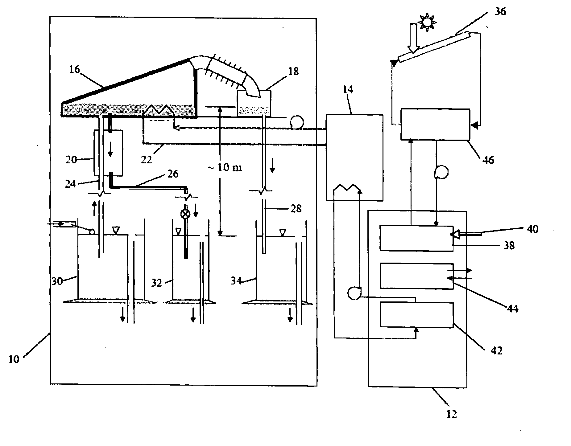
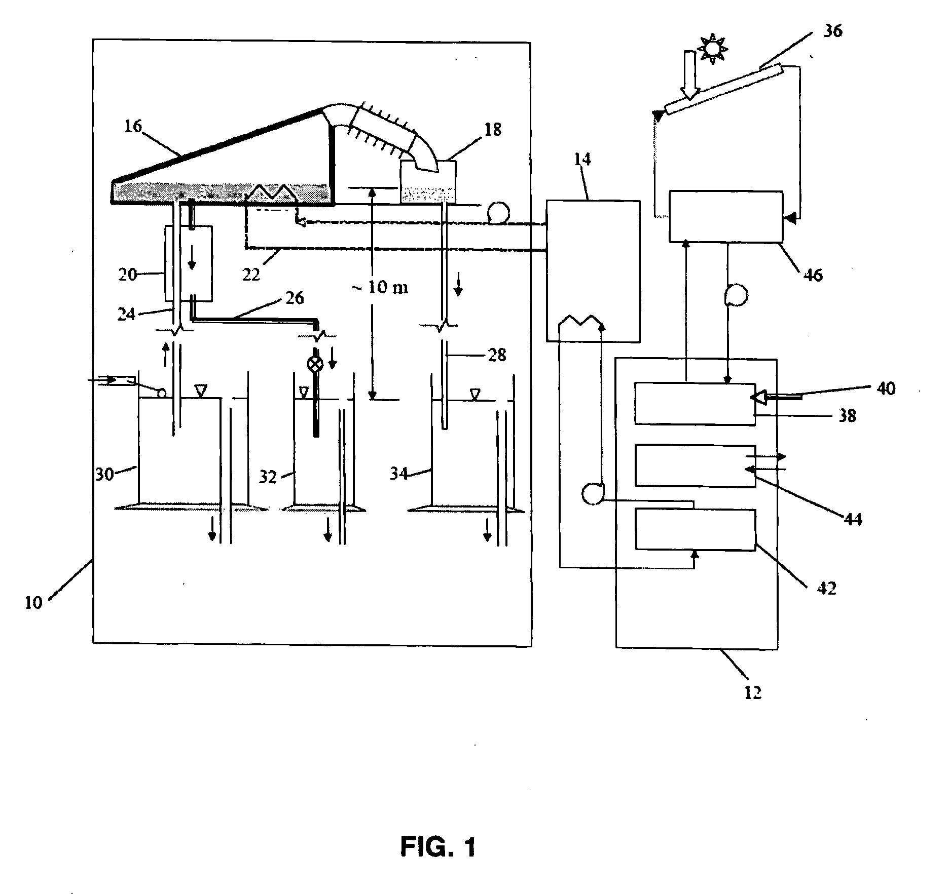
[0125]A prototype unit was constructed and experiments were conducted using direct solar energy and photovoltaic energy as heat sources. Desalination was performed on a continuous basis over 24 hours a day for several months. This prototype comprised of columns that were 10 m, equivalent to the local barometric head. The temperature of the head space of the feed water column was maintained at approximately 40-50° C., while the desalinated water column was maintained at approximately 35-45° C. The pressure in the evaporation chamber remained at approximately 0.085 atm. The specific energy required by this prototype was approximately 3,370 kJ / kg of desalinated. This system was run entirely on solar energy with direct solar heat during sunlight hours and with a 350-W DC heater powered by batteries that were charged by the photovoltaic panels during the day time. This example system was able to recover potable quality water meeting United States Environmental Protection Agency drinking ...


PUM

PropertyMeasurementUnit
Temperatureaaaaaaaaaa
Pressureaaaaaaaaaa
Temperatureaaaaaaaaaa

Abstract

This invention describes a low temperature, self-sustainable desalination process operated under natural vacuum conditions created and maintained by barometric pressure head.

Description

CROSS-REFERENCE TO RELATED APPLICATIONS[0001]This application claims priority to and the benefit of U.S. Provisional Application Ser. No. 60 / 950,076, entitled “Desalination using Low-Grade Thermal Energy”, to Nagamany Nirmalakhandan et al., filed on Jul. 16, 2007, and the specification thereof is incorporated herein by reference.BACKGROUND OF THE INVENTION[0002]1. Field of the Invention (Technical Field)[0003]The present invention relates to an apparatus and method for desalination.[0004]2. Description of Related Art[0005]Interest in the use of low grade heat sources and recovery of waste heat is growing due to increasing energy costs and declining energy sources. Examples of low grade energy sources include solar energy and heat rejected by fossil fuel-based power plants, air conditioning / refrigeration systems, and industrial processes. As a consequence of the laws of thermodynamics, thermal systems have to reject large quantities of low grade heat energy to the environment. For ex...

Claims


Application Information

Patent Timeline
IPC IPC(8): B01D3/26C02F1/04
CPCB01D1/0035B01D1/0058C02F1/14B01D5/006C02F1/046B01D3/103Y10S159/16Y10S203/04Y10S203/08Y10S203/18Y02W10/37Y02A20/124Y02A20/142Y02A20/212
Inventor NIRMALAKHANDAN, NAGAMANYGUDE, VEERA GNANESWAR
Owner ARROWHEAD CENT
Why Eureka
Try Eureka