Control device

a control device and motor technology, applied in the direction of dynamo-electric converter control, dynamo-electric gear control, elevators, etc., can solve the problems of torque ripple, uneven rotation, torque ripple, etc., to reduce vibration/noise of linear motors, reduce torque ripple of motors, reduce vibration/noise of motors

Inactive Publication Date: 2009-01-22
TOSHIBA ELEVATOR KK
View PDF6 Cites 38 Cited by
  • Summary
  • Abstract
  • Description
  • Claims
  • Application Information

AI Technical Summary

Benefits of technology

[0039]According to the present invention, the waveform of the output current supplied to the motor can be adjusted, and the torque ripple of the motor can be reduced to a large extent. As a result, the vibrations/noise of the motor can be reduced.
[0040]Moreover, the

Problems solved by technology

Therefore, torque generated by the motor pulsates since such a magnetic flux change that should originally have a sine wave shape contains the distortion, and this causes a

Method used


Image

  • Control device
  • Control device
  • Control device

Examples


first embodiment

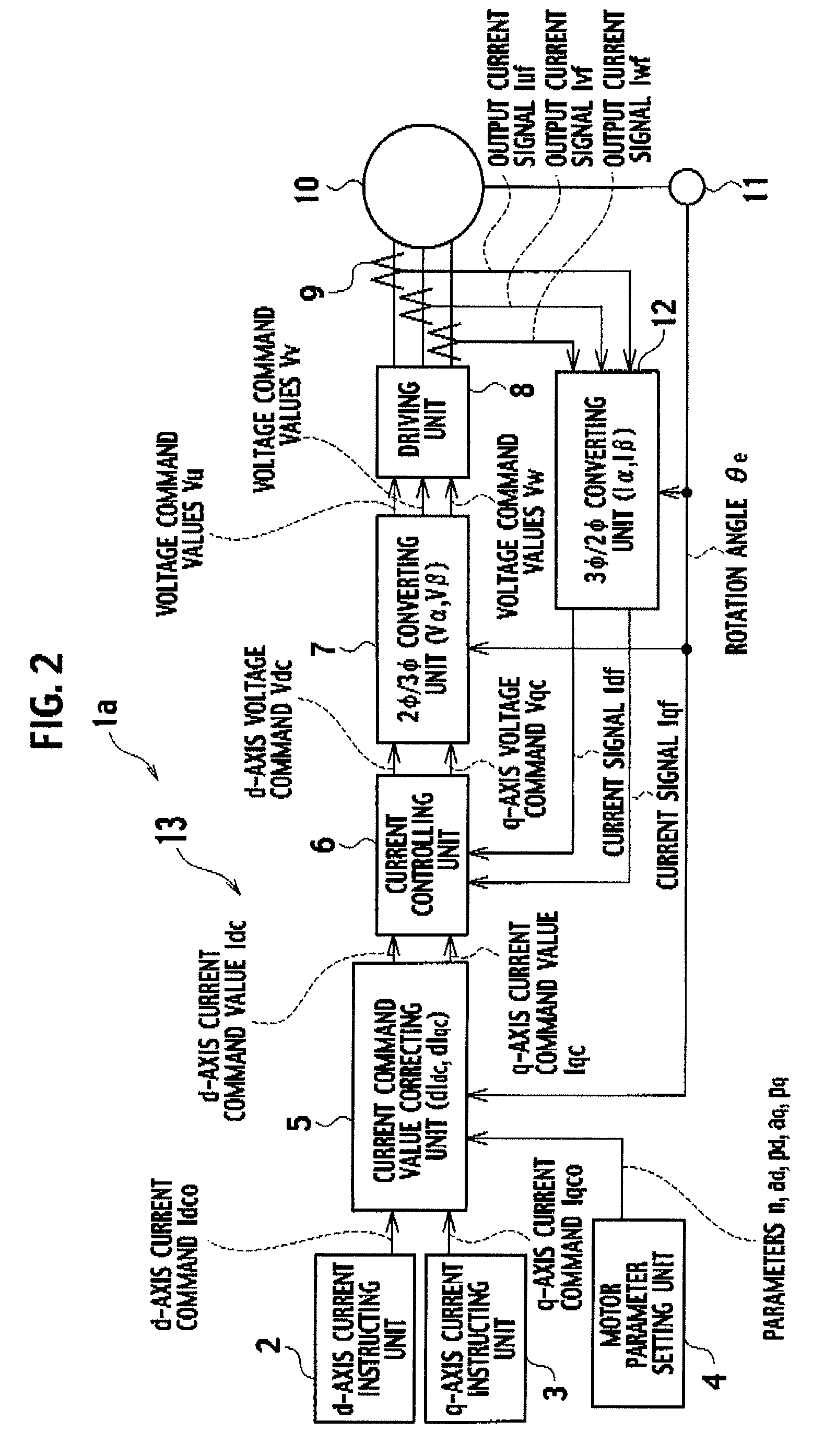
[0054]FIG. 2 is a block diagram showing a first embodiment of a control device according to the present invention.

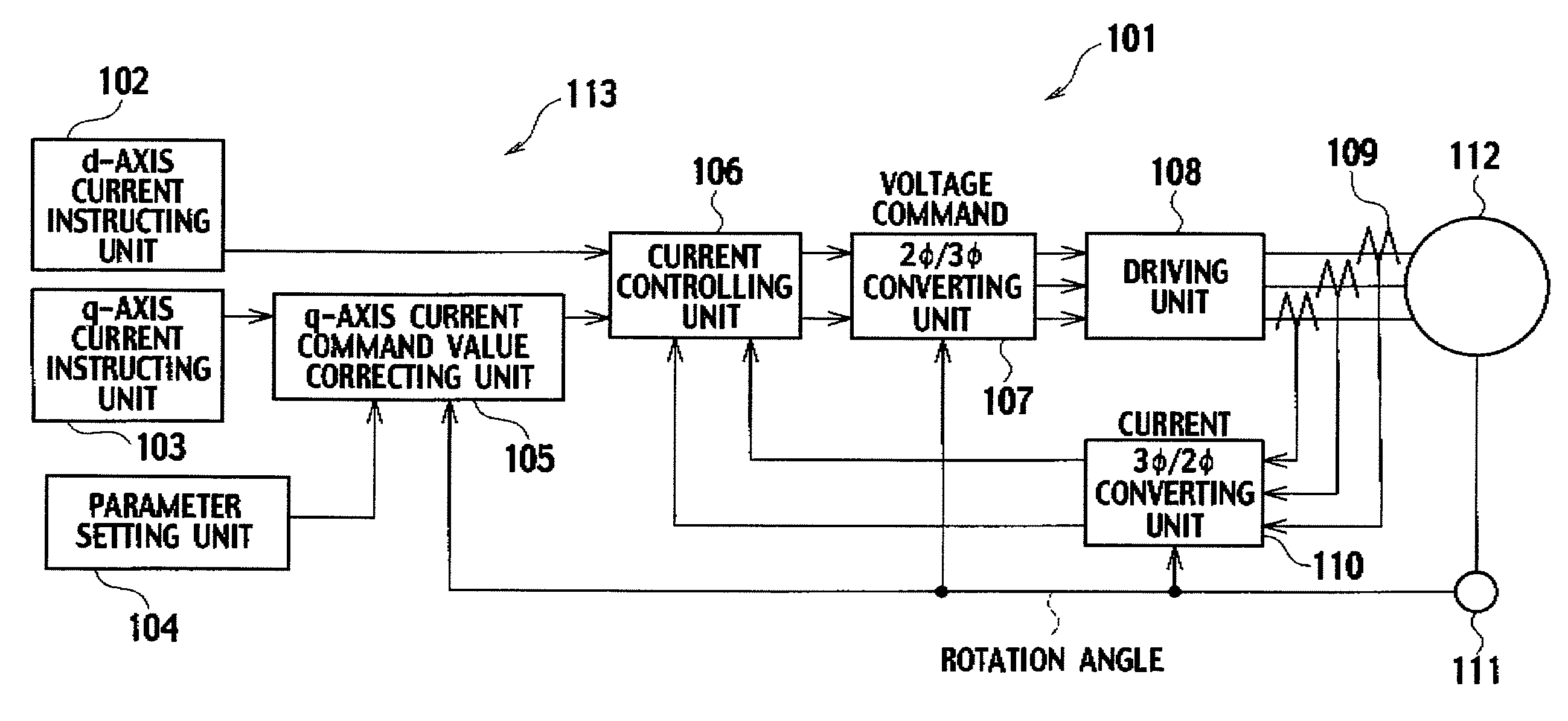
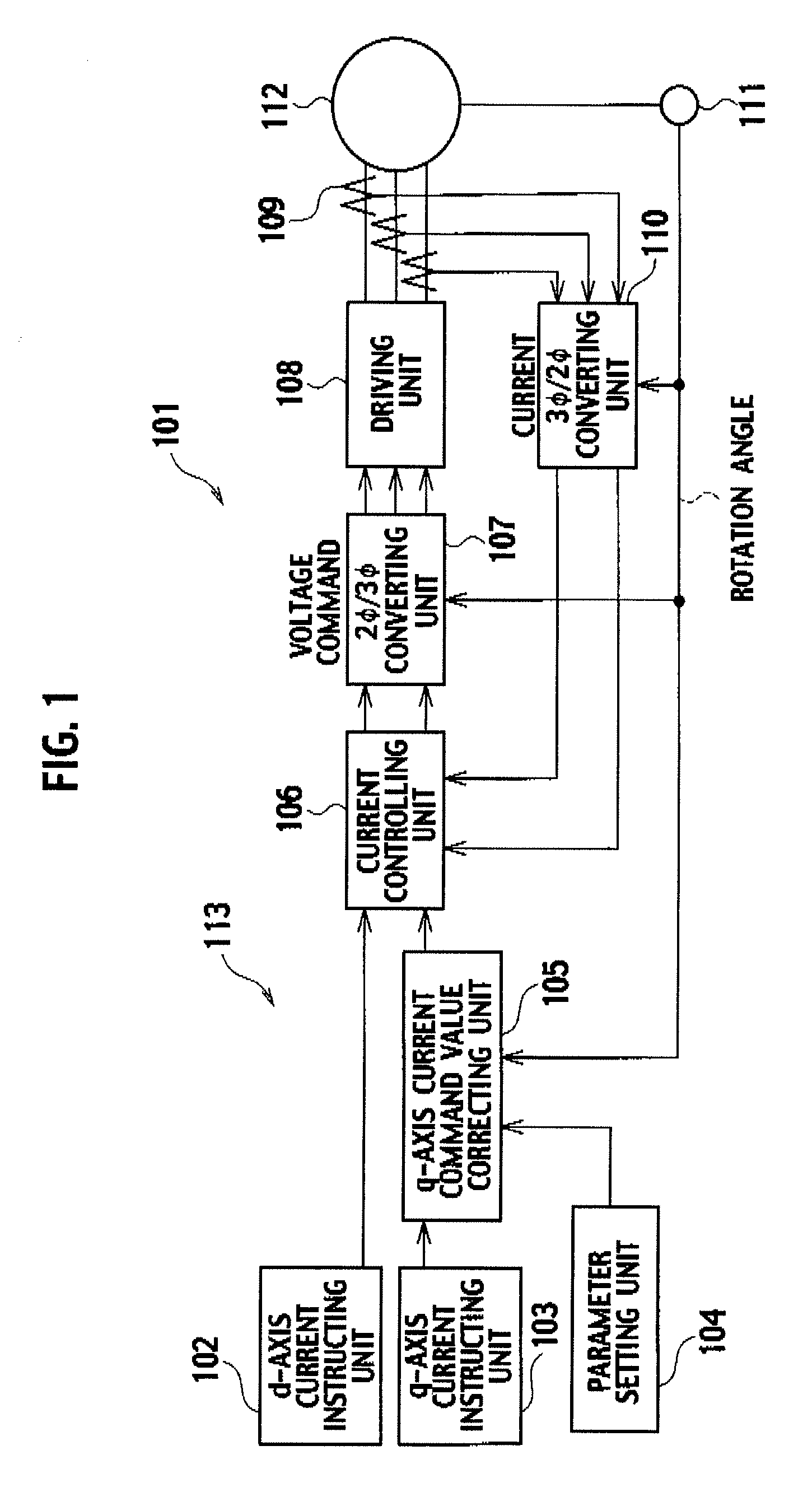
[0055]A control device 1a shown in this drawing includes: a d-axis current instructing unit 2 that outputs a d-axis current command “Idco”; a q-axis current instructing unit 3 that outputs a q-axis current command “Iqco”; and a motor parameter setting unit 4 in which parameters “n”, “ad”, “pd”, “aq”, “pq” and the like of a motor 10 are set.

[0056]Moreover, this control device 1a includes: a current command correcting unit 5; a current controlling unit 6; a 2-phase / 3-phase converting unit 7; a driving unit 8; a current detecting unit 9; a rotation angle detecting unit 11 that detects a rotation angle “θe” of the motor 10, and a 3-phase / 2-phase converting unit 12.

[0057]Here, based on the parameters “n”, “ad”, “pd”, “aq”, and “pq” of the motor 10, which are outputted from the motor parameter setting unit 4, and on a detection result of the rotation angle detecting unit 11, t...

second embodiment

[0087]FIG. 4 is a block diagram showing a second embodiment of the control device according to the present invention. Note that, in this drawing, the same reference numerals are assigned to portions corresponding to the respective portions of FIG. 2.

[0088]A different point of a control device 1b shown in this drawing from the control device 1a shown in FIG. 2 is that there are provided: a ripple detecting unit 21 that detects vibrations or noise “dFrf” of the motor 10; and a correction parameter learning unit 22 that learns parameters related to the vibrations and noise of the motor 10, for example, the parameters “ad”, “pd” and the like among the parameters “n”, “ad”, “pd”, “aq” and “pq” for use in the current command correcting unit 5 based on an output of the ripple detecting unit 21.

[0089]Next, a description will be made of detailed operations of the ripple detecting unit 21, the current command correcting unit 5, and the correction parameter learning unit 22 with reference to F...

third embodiment

[0102]FIG. 6 is a block diagram showing a third embodiment of the control device according to the present invention. Note that, in this drawing, the same reference numerals are assigned to portions corresponding to the respective portions of FIG. 2.

[0103]A different point of a control device 1c shown in this drawing from the control device 1a shown in FIG. 2 is that there are provided: a ripple assuming unit 31 that assumes a ripple “dTfdt” of the motor 10 based on the d-axis voltage command “Vd” and the q-axis voltage command “Vq”, which are outputted from the current controlling unit 6, on the current values (current signals “Idf” and “Iqf” outputted from the 3-phase / 2-phase converting unit 12) detected by the current detecting unit 9, and on the rotation angle “ω” corresponding to the rotation angle “θe” detected by the rotation angle detecting unit 11; and a correction parameter learning unit 32 that learns, from the assumed ripple “dTfdt”, the parameters related to the vibratio...


PUM


Abstract

Parameters “n”, “ad”, “pd”, “aq”, “pq” and the like of a motor parameter setting unit 4 are set so as to satisfy [Expression 23] and the like, a d-axis current command value “Idco” outputted from a d-axis current instructing unit 2 and a q-axis current command value “Iqco” outputted from q-axis current instructing unit 3 are corrected based on these parameters “n”, “ad”, “pd”, “aq” and “pq”, on a detection result of rotation angle detecting unit 11, and on the like, and a (6×n)f sine component, (6×n)f cosine component, (6×(n+1))f sine component and (6×(n+1))f cosine component of torque “T” shown in [Expression 22] are made zero. In such a way, 6×n and 6×(n+1) ripple components and the like, which are generated in a motor provided in elevator equipment or the like, are suppressed, and a torque ripple of the motor is reduced to a large extent.

Description

TECHNICAL FIELD[0001]The present invention relates to a control device that controls a motor for use in elevator equipment.BACKGROUND ART[0002]In general, a permanent magnet synchronous motor can be fabricated to be more compact than an induction motor with respect to the same output, and accordingly, has been going to be used for drive units of a variety of systems in recent years.[0003]Incidentally, in the permanent magnet synchronous motor, a change of an armature magnetic flux that rotates a magnetic pole is not a sine wave of a rotation angle, but contains a distortion. Therefore, torque generated by the motor pulsates since such a magnetic flux change that should originally have a sine wave shape contains the distortion, and this causes an uneven rotation and the like. Moreover, unbalance of a coil of the motor, an error in a sensor system that detects a current, and the like also cause such a torque ripple.[0004]As a reduction method of the torque ripple, there is a method as...

Claims


Application Information

Patent Timeline
IPC IPC(8): H02P21/00H02P27/04H02P21/05H02P21/22H02P23/04H02P25/06H02P27/06
CPCH02P25/06H02P21/0035B66B1/308H02P21/22
Inventor TONAMI, YOSUKEMORISHITA, MIMPEI
Owner TOSHIBA ELEVATOR KK
Why Eureka
Try Eureka