PON equipment capablel of displaying connection state and logical link identifier

a technology of logical link and equipment, applied in the field of passive optical network equipment, can solve the problems of high cost, inability to meet the requirements of high speed transmission application, and inability to save establishment and maintenance costs, and achieve the effect of eliminating network errors

Inactive Publication Date: 2009-01-22
INVENTEC MULTIMEDIA & TELECOM TIANJIN0
View PDF5 Cites 11 Cited by
  • Summary
  • Abstract
  • Description
  • Claims
  • Application Information

AI Technical Summary

Benefits of technology

[0012]In a point to multi-point (P2MP) network architecture, once being disposed with the PON equipment of the present invention, the OLT at the central office acquires the connection state and the identification of the optical communication equipment, and the ONU at the customer premise displays the LLID of itself, so as to offer the identification information required by the network administrators at the central office to eliminate the network errors. If an error occurs to the ONU connection, the network administrator at the central office can observe the connection state provided by the connected OLT display unit according to the ONU identification information provided by the user, so as to further determine the exact problem.

Problems solved by technology

As the rapid development of Internet, the conventional network cannot meet the requirements of high speed transmission application.
However, since a large amount of the optical fiber is required, the cost is high.
Since a small number of the optical fiber is required, the cost for establishment and maintenance is saved.
However, the common front-line maintenance personnel can only maintain the equipments after acquiring the messages from the personnel having the administration priority.
Therefore, not only the maintenance process becomes complicated and inconvenient for being managed, but the disconnection cannot be informed and processed immediately after it occurs.
Therefore, when the system has a problem, the difficulty in detection is increased, and thus, it is not a desirable design but needs to be improved.

Method used


Image

  • PON equipment capablel of displaying connection state and logical link identifier
  • PON equipment capablel of displaying connection state and logical link identifier
  • PON equipment capablel of displaying connection state and logical link identifier

Examples


Embodiment Construction

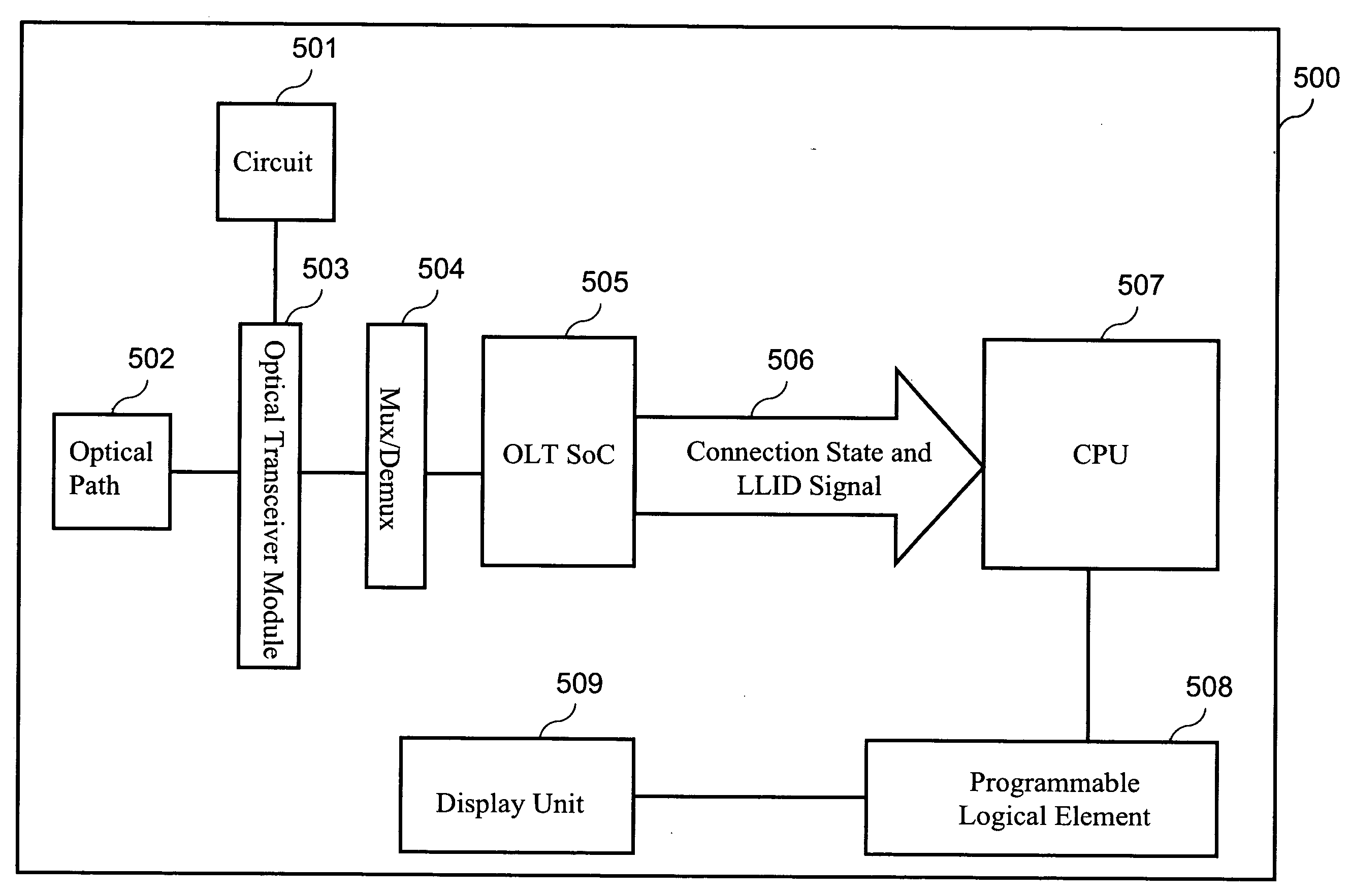
[0023]The present invention is mainly directed to a PON equipment capable of displaying a connection state and a logical link identifier (LLID). As described above, the PON system is substantially a topology in a P2MP form, and hereinafter, the role that the LLID plays in the packet transmission process in the PON system is illustrated with reference to the drawings, and how the ONU acquires the LLID assigned by the OLT through the MPCP is illustrated in brief.

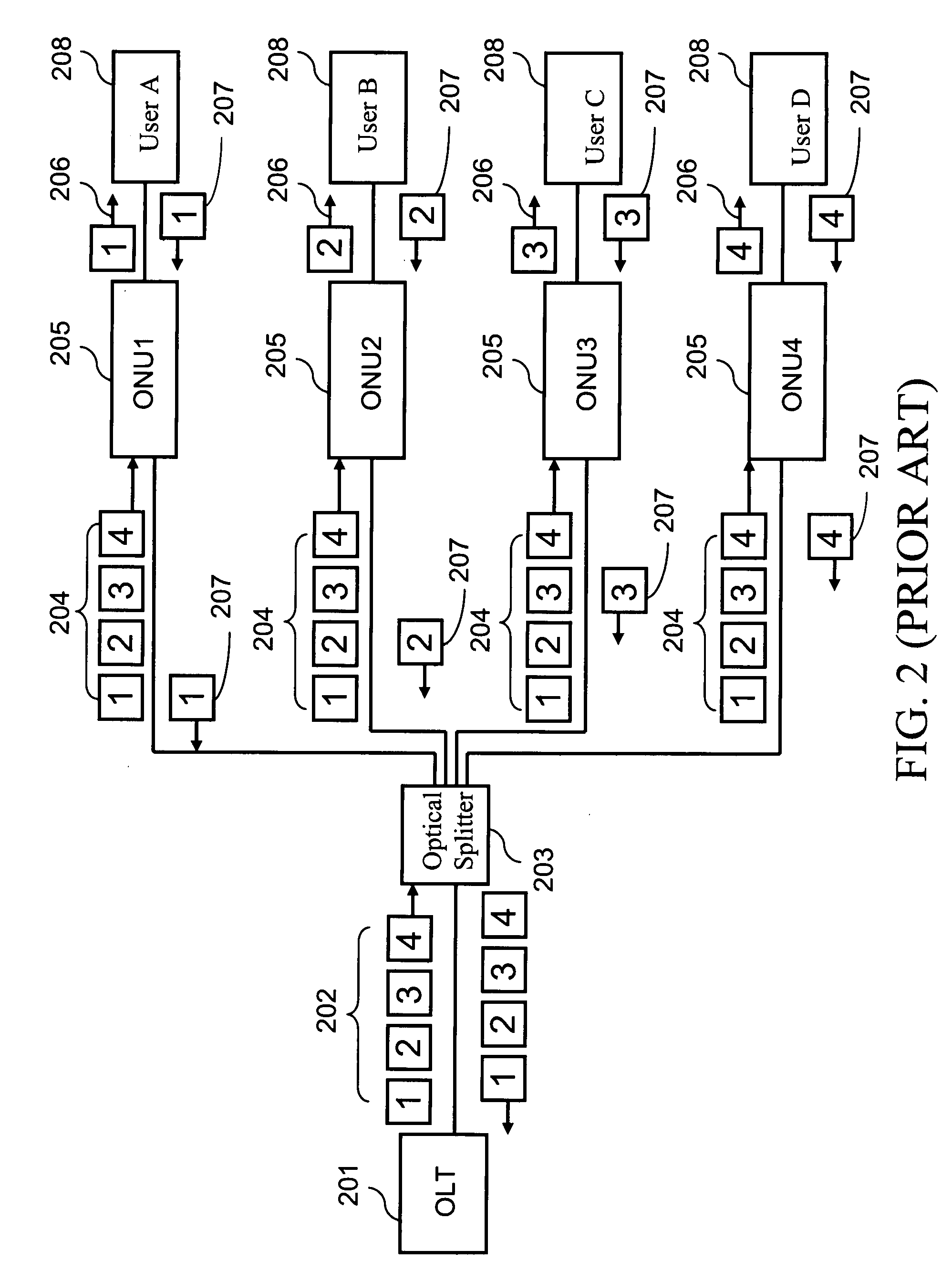
[0024]First, the packet transmission process in the PON system is illustrated with reference to FIG. 2, in which a central office equipment OLT 201, an optical splitter 203, four customer premise equipments ONU 205, and four users 208 together constitute a typical PON system. The users 208 represent devices connected with the ONU, such as computers and handheld personal digital assistants (PDAs). Since the PON is a topology in the form of P2MP, the OLT transmits downlink packets to each user by means of broadcasting. When the ...


PUM


Abstract

A passive optical network (PON) equipment capable of displaying a connection state and a logical link identifier (LLID) is provided, which aims at solving a problem that equipments in the conventional PON system cannot display connection state and LLID. The PON equipment displays the connection state and the LLID through a programmable logic element and a display unit by utilizing characteristics of multi-point control protocol (MPCP) and LLID, so as to achieve the efficacy of displaying the connection state and the LLID.

Description

BACKGROUND OF THE INVENTION[0001]1. Field of Invention[0002]The present invention relates to a passive optical network (PON) equipment capable of displaying a connection state and a logical link identifier (LLID). More particularly, the present invention relates to a PON equipment capable of displaying the connection state and a LLID through a programmable logic element and a display unit by means of utilizing the characteristics of multi-point control protocol (MPCP) and LLID.[0003]2. Related Art[0004]As the rapid development of Internet, the conventional network cannot meet the requirements of high speed transmission application. However, as the mature of the optoelectronics industry and the diversification of product applications, a wide bandwidth is provided for the rapidly developed Internet. Compared with the conventional cable transmission mode, the optical fiber transmission has the characteristics of a large capacity, a low consumption, and anti-electromagnetic interference...

Claims


Application Information

Patent Timeline
Patent Type & Authority Applications(United States)
IPC IPC(8): H04B10/20
CPCH04Q11/0067H04Q2011/0088H04Q2011/0083H04Q2011/0064
Inventor LU, KEVIN
Owner INVENTEC MULTIMEDIA & TELECOM TIANJIN0
Why Eureka
Try Eureka