Steady-state and transitory control for transmission between engine and electrical power generator

Inactive Publication Date: 2009-01-22
S O E TECH
View PDF17 Cites 104 Cited by
  • Summary
  • Abstract
  • Description
  • Claims
  • Application Information

AI Technical Summary

Benefits of technology

[0009]An object of the present invention is therefore to provide a high efficiency generator system and a continuo

Problems solved by technology

Hence, operating the engine at constant speed when load demand varies significantly yields higher fuel costs, increased emission of pollutants, higher noise level, and higher maintenance costs.
This, however, raises the problem of continuously converting the variable speed of the engine into a constant speed drive to operate the generator at a steady frequency through a fixed ratio gearbox.
However, Cronin's invention is meant to react to an intrinsically variable engine speed and has no view (scheme) of controlling said engine for efficiency purposes.
Although such a system may operate properly with slowly changing load power demand, it remains a substantial challenge to preserve the quality of the supplied current when sudden changes of load demand are experienced.
This, is mainly due to transients responsive to inertia and delays in the system.
Many engine/CVT systems have been developed which can perform satisfactorily in a vehicle, but no

Method used


Image

  • Steady-state and transitory control for transmission between engine and electrical power generator
  • Steady-state and transitory control for transmission between engine and electrical power generator
  • Steady-state and transitory control for transmission between engine and electrical power generator

Examples


Embodiment Construction

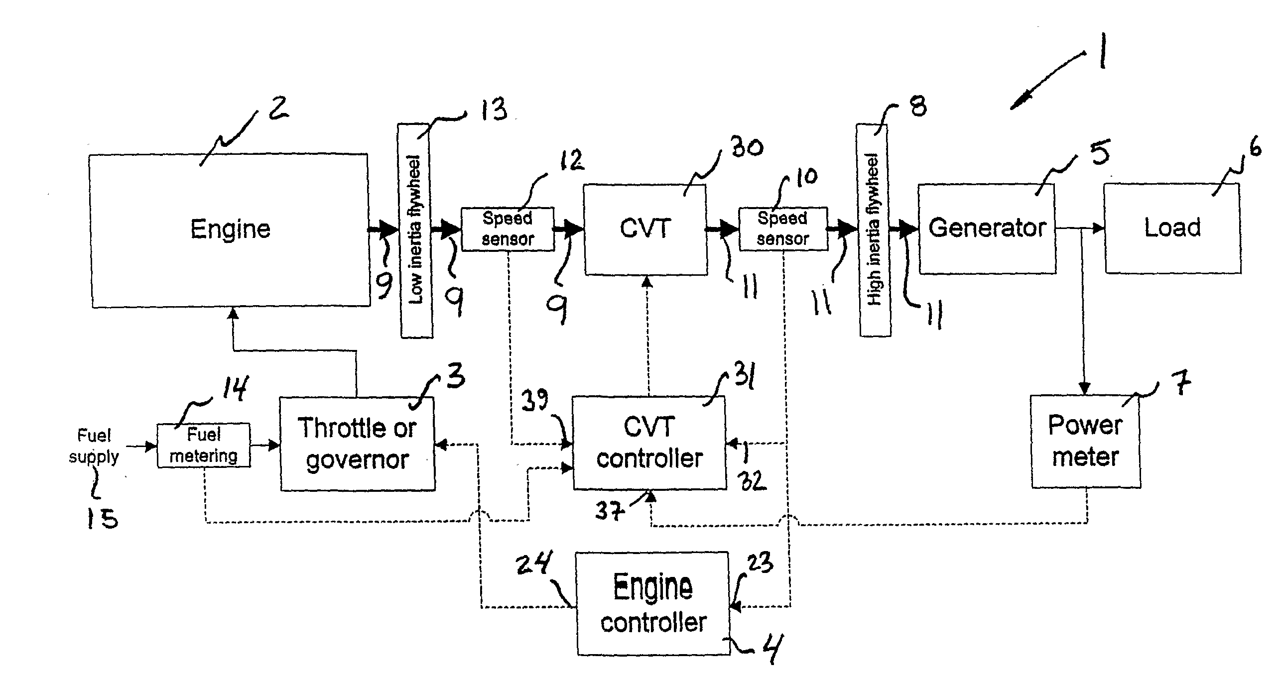
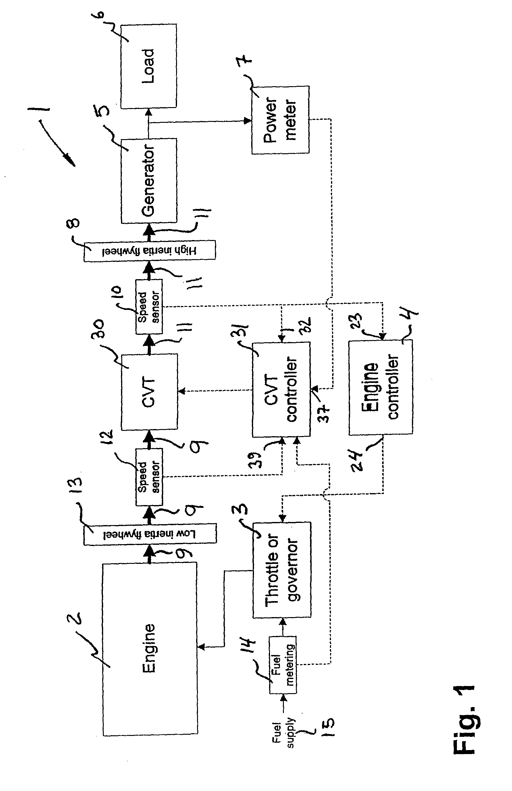
[0029]A continuously variable transmission system and a high efficiency generator system using same are generally identified by numeral 1, as illustrated in FIG. 1. The system described hereinafter will provide a stable output to an apparatus from a variable source of mechanical power through the use of a continuously variable transmission system provided with an appropriate controller. Furthermore, it is contemplated that the system provide a stable rated electrical output from a generator while performing engine speed modulation according to instant electrical power demand to improve energetic efficiency in a generator system.

[0030]The continuously variable transmission system comprises a CVT device 30 comprising an input drive shaft 9 for connection to the output of a mechanical power source such as internal combustion engine 2. An input speed sensor 12 is responsive to the rotation speed of shaft 9 and provides an input speed signal of the transmission 30 or an output speed sign...


PUM


Abstract

A system (1) for transforming a variable output into an input having a desired speed value, including a transmission (30) receiving the output having a first speed (Ve) and producing the input having a second speed (Vgen), first, second and third sensors (12,10,7) producing data (39,32,37) corresponding to the first speed (Ve), second speed (Vgen) and a power demand (Pdem) for the input, a ratio set point controller (34), a ratio controller (36) and a speed controller (4). The ratio set point controller (34) receives the data (39,32,37) and calculates an available power (Pav), a stability level of the system (S,U1,U2), a desired value for the first speed (Ve), and a desired value and rate of change for the transmission ratio. The ratio controller (36) interfaces the ratio set point controller (34) and actuates the transmission (30) to change the transmission ratio to the desired value following the desired rate of change. The speed controller (4) changes the first speed (Ve) until the second speed (Vgen) corresponds to the desired speed value.

Description

CROSS-REFERENCE TO RELATED APPLICATION[0001]The present patent application claims priority on Canadian Patent Application No. 2,479,890, filed on Sep. 27, 2004.FIELD OF THE INVENTION[0002]The present invention generally relates to mechanical transmission systems and engine driven electrical power generator systems. More specifically, the present invention is concerned with a continuously variable transmission system that can be advantageously used in a power generator system to provide constant speed drive of a generator to supply regulated power to a variable load, while enabling continuous modulation of engine speed for operation in an optimal efficiency range.BACKGROUND ART[0003]Generator systems have been used for years to supply electrical power to a load from a source of mechanical energy, such as a power take-off (PTO) of an internal combustion engine, driving a permanent magnet generator. Since the load must generally be supplied with alternating current power at a substanti...

Claims


Application Information

Patent Timeline
IPC IPC(8): F16H15/38G06F17/00F16H59/36H02P9/06
CPCF16H15/38F16H2302/04F16H61/6648
Inventor BEAUDOIN, SAMUEL
Owner S O E TECH
Why Eureka
Try Eureka