Implantable middle ear hearing device having tubular vibration transducer to drive round window

a technology of tubular vibration and hearing device, which is applied in the field of implantable middle ear hearing device having tubular vibration transducer to drive a round window, can solve the problems of complicated and time-consuming operation of piezoelectric transducer inside the middle ear cavity, make people uncomfortable before they are used to the inserted device, etc., and achieves the effect of high efficiency sound delivery and easy hearing loss compensation

Active Publication Date: 2009-01-22
KYUNGPOOK NAT UNIV IND ACADEMIC COOP FOUND
View PDF14 Cites 114 Cited by
  • Summary
  • Abstract
  • Description
  • Claims
  • Application Information

AI Technical Summary

Benefits of technology

[0043]As set forth above, the middle ear implantable hearing device of the present invention directly transmits sound vibration in response to the vibration of the miniature transducer stored inside the tubular member without through the ear drum and the ossicle, so that high efficiency sound delivery is achievable and hearing loss compensation are easy.

Problems solved by technology

People with hearing loss wears hearing device inserted into the ear, which makes the people very uncomfortable before they are accustomed to the inserted device.
It is also inconvenient to attach or detach the device.
However, this scheme has drawbacks in that the operation of implanting a piezoelectric transducer inside a middle ear cavity is complicated and time consuming.
However, the electromagnetic vibrator type transducer can be implanted only in the presence of the ossicle, and has to be clamped for a long time, which may disadvantageously burden the ossicle.
However, this scheme has drawbacks of poor practicability.
Due to the relatively large distance between the electronic coil and the permanent magnet in the round window, a considerably large signal current is applied, thereby increasing the consumption of battery power.
However, this scheme inevitably consumes a large amount of energy compared to the hearing device of Symphonix, Otologics, and St.
Thus, it is not advantageous to apply this scheme to the middle ear implantable hearing device that has limited battery capacity.
Therefore, the application of the tube cannot be regarded as an inventive concept of this device.
Firstly, the structure of each sound coupler is too complicated, so that a miniature sound coupler cannot be easily fabricated or welded, thereby increasing manufacturing costs.
This structure also requires very complicated and difficult processes, such as welding a small connector loop to the center of the membrane of a very thin Titanium film and hermetically sealing the entire structure.
Secondly, as another drawback of the hearing device of Engebreison et al., the ossicle of a patient should be cut such that an output from the receiver is not feed back to an adjacent sound coupler of the microphone.
Accordingly, the device is more bulky and complicated.
Accordingly, this structure fails to provide clear sound to the user.
However, this method has same limitations as point out in the Engebreison et al.
's method, due to they use long liquid tube which severely reduces high frequency response.
Further, since the vibrator has to be fixed using only the fascia, it is difficult to guarantee that the vibrator stably remain in position for a long time after the operation.
The fixing process is insecure, and this scheme is rarely applicable to patients having severe hearing loss since the maximum driving force of the vibrator is dependent on the maximum driving force of the floating mass vibrator.
Therefore, a great amount of sound attenuation and distortion is followed, and the temporal bone has to be cut in when the operation is performed.
This configuration, however, may cause loss to the transmission of pressure.

Method used


Image

  • Implantable middle ear hearing device having tubular vibration transducer to drive round window
  • Implantable middle ear hearing device having tubular vibration transducer to drive round window
  • Implantable middle ear hearing device having tubular vibration transducer to drive round window

Examples


Embodiment Construction

[0056]Hereinafter, an implantable middle ear hearing device having a tubular vibration transducer to vibrate a round window according to the present invention will be described more fully with reference to the accompanying drawings, in which exemplary embodiments thereof are shown.

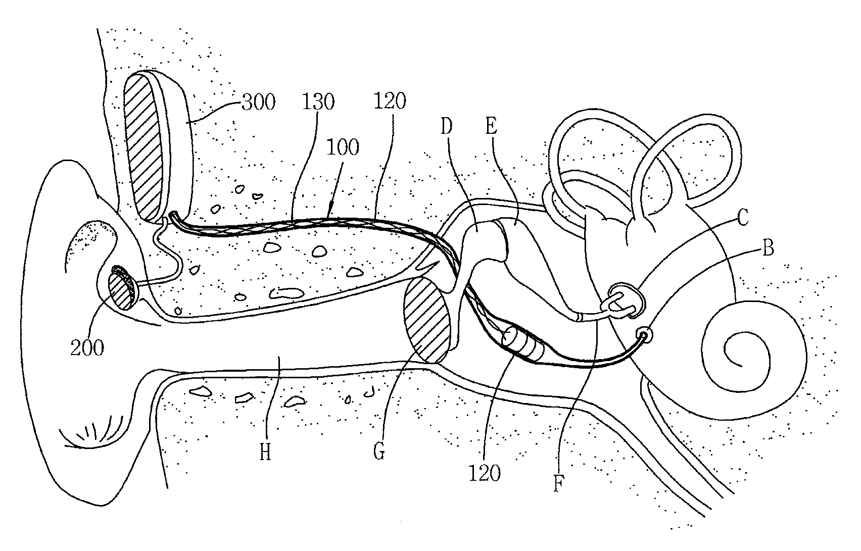
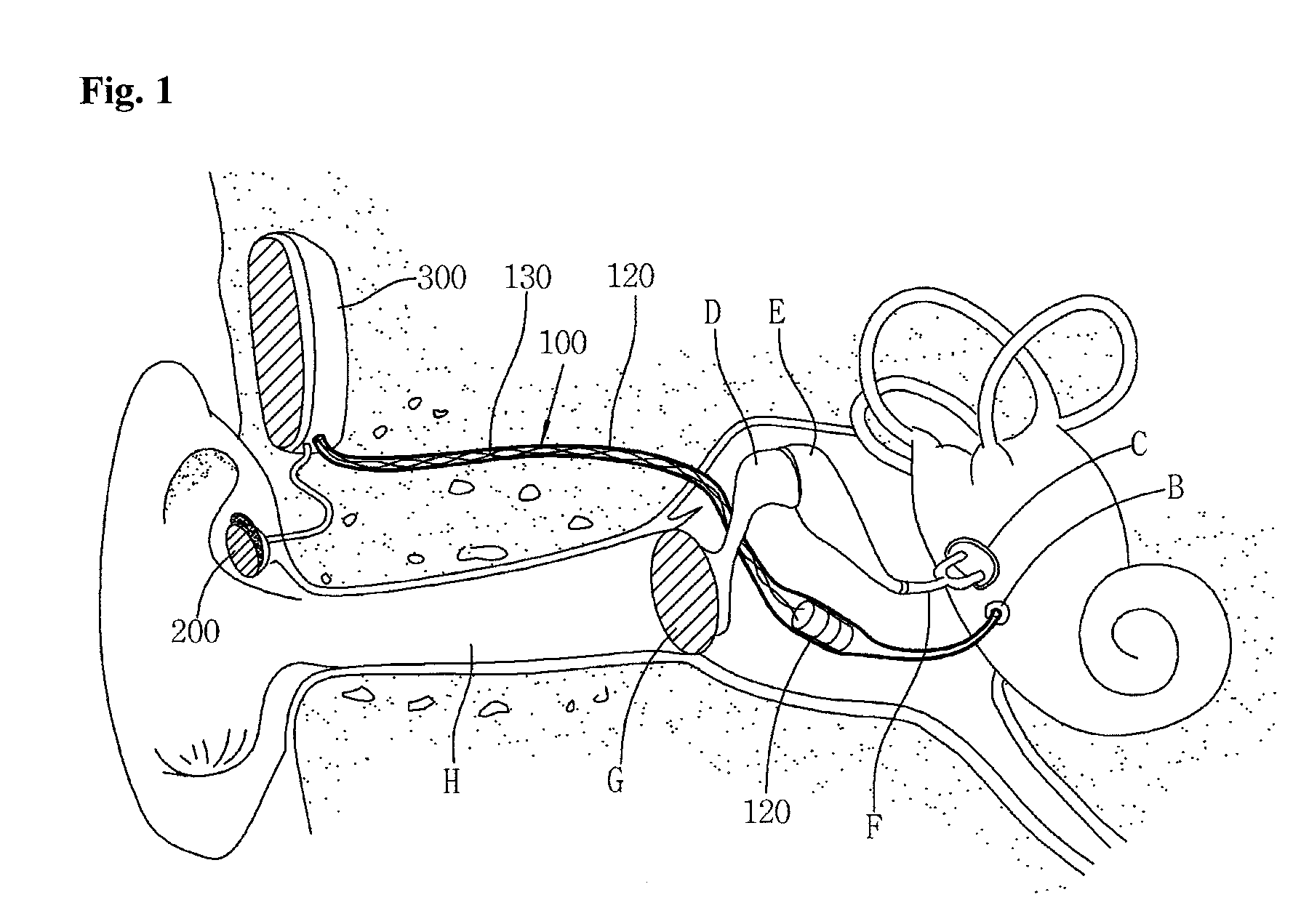
[0057]Of the accompanying drawings, FIG. 1 illustrates the structure and operation principle of an implantable middle ear hearing device having a tubular vibration transducer to vibrate a round window according to an embodiment of the present invention.

[0058]Firstly, the basic structure of the implantable middle ear hearing device according to an embodiment of the present invention will be described with reference to FIG. 1.

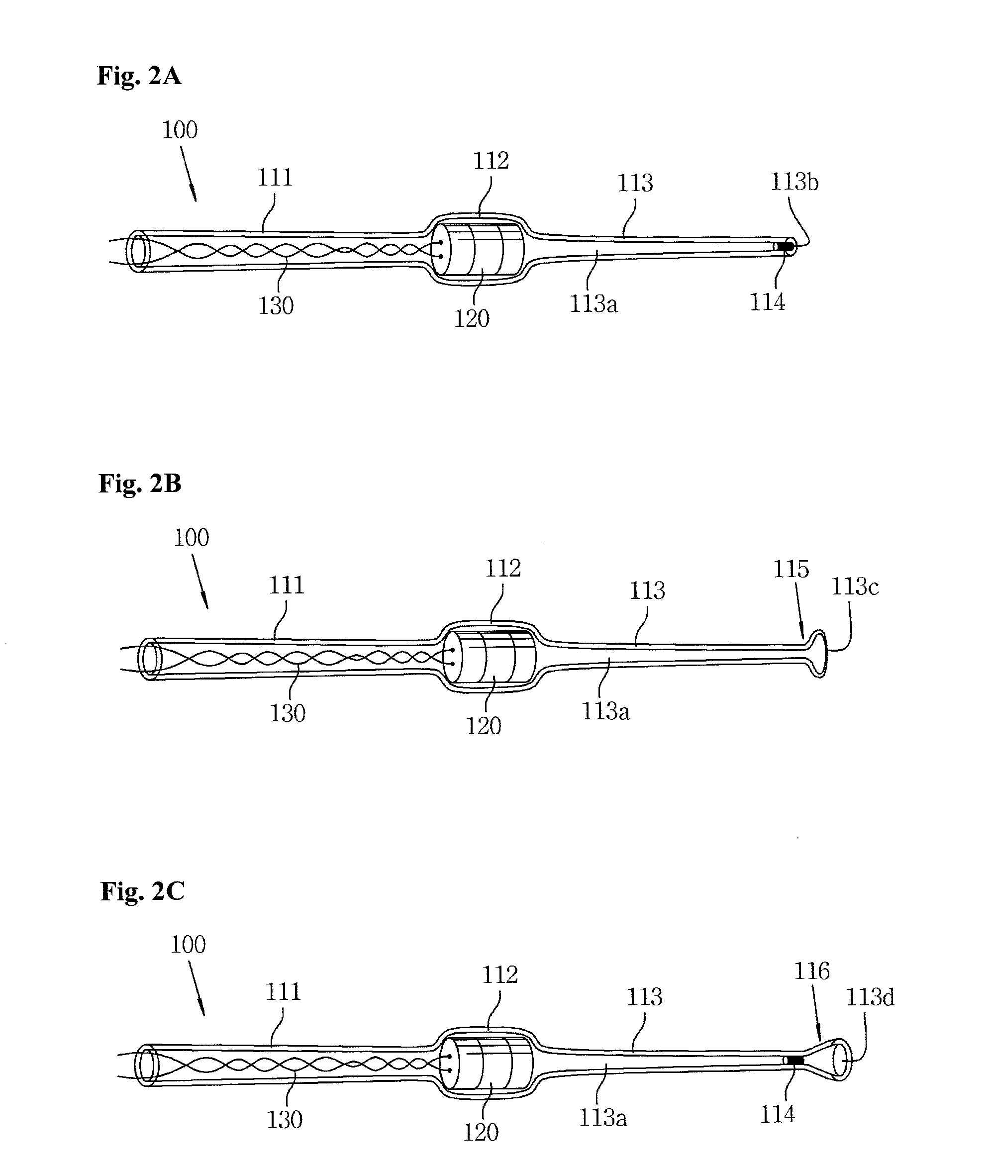
[0059]The implantable middle ear hearing device 100 of this embodiment includes a tubular member 110, a vibrating unit 120 and signal cords 130. The hearing device 100 cooperates with a microphone 200, which is attached to an ear of a user in order to detect sound from outside, and a si...


PUM


Abstract

An implantable middle ear hearing device having a tubular vibration transducer to drive a round window is designed to input sound to a round window opposite an oval window in an inner ear. The tubular vibration transducer has a unique structure that does not attenuate the magnitude of a signal, particularly, in a high frequency band. Sound delivery effect is much higher than those of conventional schemes. It is also possible to minimize difficulties associated with and problems resulting from the operation, which the conventional methods would have. Further, the transducer can have a relatively less compact than ossicle contact type transducers, and thus be easily fabricated. The hearing device can be applied to a sensorineural hearing loss patient with the ossicle damaged. Moreover, since sound is directly transmitted without through the ear drum and the ossicle, high efficiency sound delivery is achievable and hearing loss compensation are easy.

Description

CLAIM OF PRIORITY[0001]This application claims the benefit of Korean Patent Application No. 10-2007-0072666 filed on Jul.20, 2007, in the Korean Intellectual Property Office, the disclosure of which is incorporated herein by reference.BACKGROUND OF THE INVENTION[0002]1. Field of the Invention[0003]The present invention relates to an implantable middle ear hearing device having a tubular vibration transducer to drive a round window. More particularly, the implantable middle ear hearing device of the present invention is designed to input sound to the round window opposite an oval window in an inner ear using the tubular vibration transducer having a unique structure that does not attenuate the magnitude of a signal, particularly, in a high frequency band.[0004]2. Description of the Related Art[0005]In general, about 15% of the world population has mild to severe hearing loss, and about 1 to 2% of the people with hearing loss cannot hear better using a hearing device that transmits so...

Claims


Application Information

Patent Timeline
Patent Type & Authority Applications(United States)
IPC IPC(8): A61F11/00H04R25/00
CPCH04R25/606A61F2/18
Inventor CHO, JIN-HOPARK, IL-YONGSEONG, KI-WOONG
Owner KYUNGPOOK NAT UNIV IND ACADEMIC COOP FOUND
Why Eureka
Try Eureka