Method and apparatus for synchronous switching of fuel injection control signals

a technology of control signals and fuel injection, which is applied in the direction of electrical control, process and machine control, instruments, etc., can solve the problems of not providing signals for switching, and achieve the effects of improving driveability, reducing noise, and increasing torqu

Inactive Publication Date: 2009-01-22
DELPHI TECH INC
View PDF6 Cites 38 Cited by
  • Summary
  • Abstract
  • Description
  • Claims
  • Application Information

AI Technical Summary

Benefits of technology

[0007]One advantage of the present invention is that it provides for improved driveability compared to current technology implementations. Specifically, the present invention allows the engine management system, for example in high load conditions, to switch from CNG fuel back to liquid fuel when greater torque is needed or desired for improved driveability. This commutation is controlled so as to not disrupt an ongoing fuel injection of CNG fuel.
[0008]A method of operating an internal combustion engine according to the invention includes a number of steps. First, providing a fuel type command indicative of a desired fuel type selected from the group comprising a liquid fuel (e.g., multifuel) and compressed natural gas (CNG) fuel. Second, producing a plurality of fuel injection signals defining respective fuel injection events for a corresponding plurality of cylinders of the engine. Finally, switching, in response to the fuel type command, the plurality of fuel injection signals from a first set of injectors to a second, different set of injectors that is associated with the desired fuel type wherein the switching is performed, for each fuel injection signal, after a respective fuel injection event has been completed. The fuel type command is synchronized, in a preferred embodiment, to the engine crankshaft to enable the injector-by-injector changeover.
[0009]An apparatus according to the invention is also presented.
[0010]Other features and aspects of the invention are further presented.

Problems solved by technology

However, such a conventional approach does not provide for switching of the signals in a manner synchronized to the timing of the engine crankshaft.

Method used


Image

  • Method and apparatus for synchronous switching of fuel injection control signals
  • Method and apparatus for synchronous switching of fuel injection control signals
  • Method and apparatus for synchronous switching of fuel injection control signals

Examples


Embodiment Construction

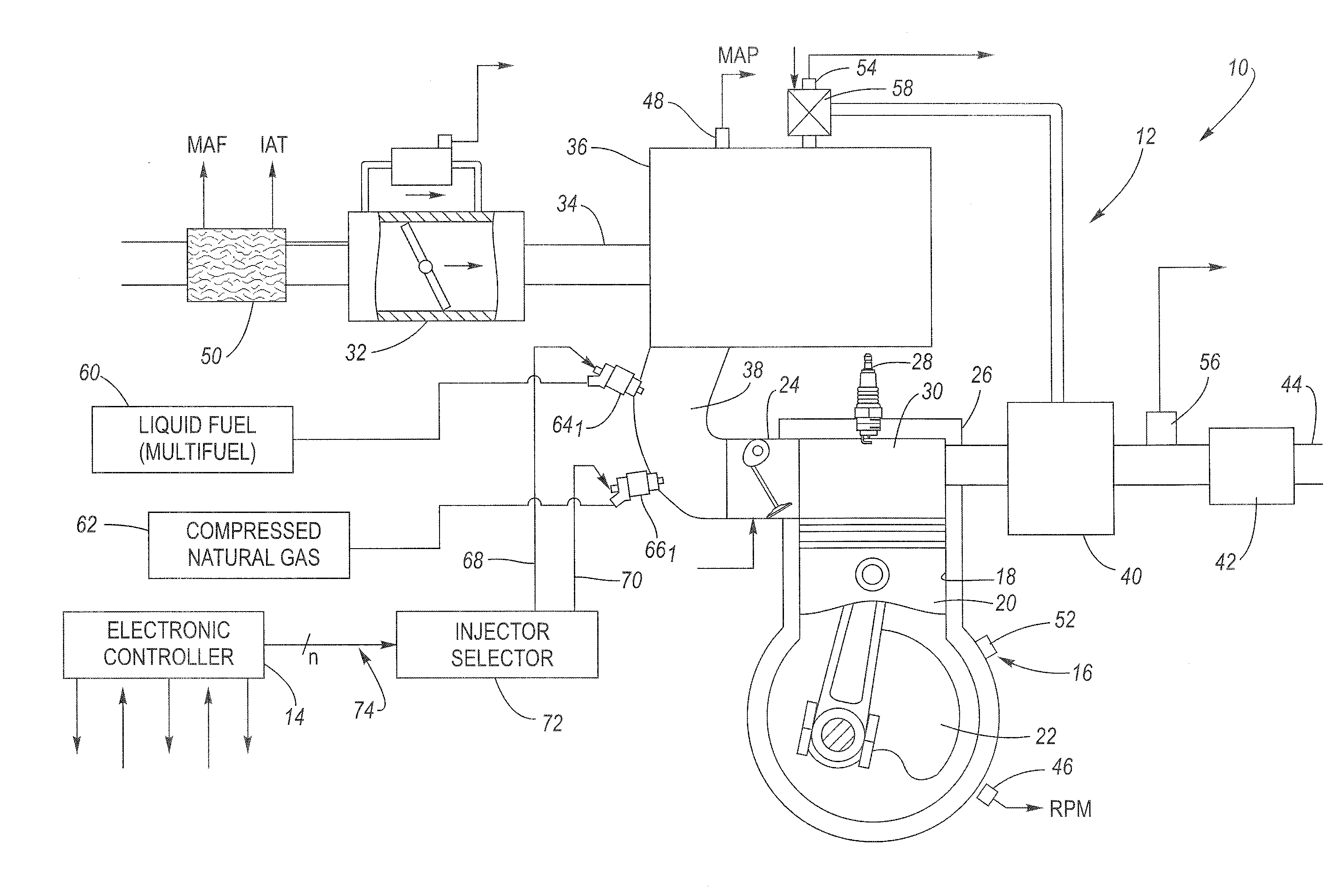
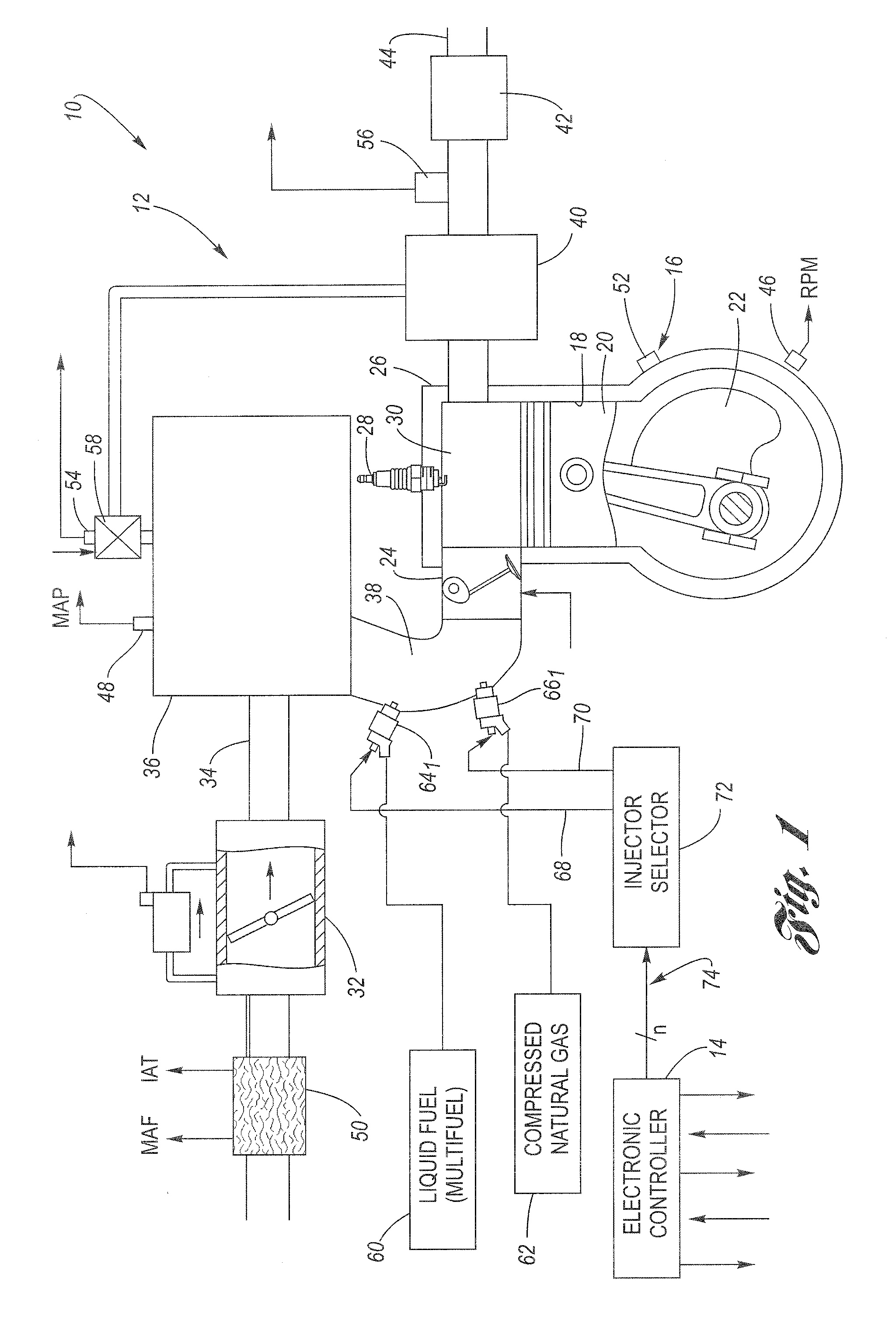
[0017]Referring now to the drawings, wherein the Figures are for the purpose of illustrating an embodiment of the invention only, FIG. 1 shows an internal combustion engine system 10 including an internal combustion engine 12 controlled by an electronic engine controller 14, all in accordance with an embodiment of the present invention.

[0018]The exemplary internal combustion engine 12 may be a spark-ignition engine that includes base engine components, sensing devices, output systems and devices, and a control system. It should be understood that the principles of the present invention may also be employed in compression ignition type internal combustion engines (e.g., diesel cycle).

[0019]Electronic controller 14 is configured via suitable programming to contain various software algorithms and calibrations, electrically connected and responsive to a plurality of engine and vehicle sensors, and operably connected to a plurality of output devices. Controller 14 includes at least one m...


PUM


Abstract

An engine management and fuel delivery system allows an internal combustion engine to operate on liquid fuel such as gasoline, ethanol or a blend thereof, or compressed natural gas (CNG). A first set of fuel injectors is configured to deliver liquid fuel to the cylinders. A second set of fuel injectors is configured to deliver natural gas to the cylinders. An electronic controller is configured to generate fuel injection signals for one of the sets of injectors. An injector selector is configured to direct such fuel injection signals to either the first set of fuel injectors or the second set of fuel injectors based on a fuel type command. The fuel type command is indicative of a desired fuel type selected from either liquid fuel or CNG fuel. The fuel type command is synchronized in accordance with an engine crankshaft position signal in order to coordinate the switchover, for each one of the fuel injection signals, one by one, as each fuel injection event is completed.

Description

TECHNICAL FIELD[0001]The present invention relates generally to internal combustion engine control systems, and more particularly to a method and apparatus for operating an internal combustion engine.BACKGROUND OF THE INVENTION[0002]It is known to provide an engine control system for a modern internal combustion engine that includes an electronic controller operable to monitor engine operating conditions and operator inputs, and operable to control various systems and actuators based upon the monitored conditions and inputs. The conventional engine control system is electrically connected to a plurality of engine and vehicle sensors that monitor engine operating conditions and operator demands. Monitored operating conditions may include, for example, engine rotational speed and position, engine load, vehicle speed, engine coolant temperature, intake air temperature, engine air / fuel ratio, accessory demands, and the operator's demand for power. The engine control system is operably c...

Claims


Application Information

Patent Timeline
Patent Type & Authority Applications(United States)
IPC IPC(8): F02D28/00
CPCF02D19/0647F02D41/0025F02D41/0027F02D41/047F02M25/0756F02D41/008F02D19/061F02D19/0615F02D19/0636F02D19/0692Y02T10/36F02M26/48Y02T10/30
Inventor VOLPATO, ORLANDO
Owner DELPHI TECH INC
Why Eureka
Try Eureka