Black plant steam furnace injection

a technology of fluidized bed and boiler, which is applied in the direction of steam generation plants, combustion types, separation processes, etc., can solve the problems of lowering the water level in the boiler circulation system, uncooled tubes exposed to residual heat of uncooled parts of solid separators, and damage to uncooled tubes. , to achieve the effect of reducing or eliminating additional costs, reducing or eliminating, and reducing boiler pressur

Active Publication Date: 2009-01-29
THE BABCOCK & WILCOX CO
View PDF7 Cites 10 Cited by
  • Summary
  • Abstract
  • Description
  • Claims
  • Application Information

AI Technical Summary

Benefits of technology

[0014]The present invention is drawn to a system and method for reducing or eliminating the additional cost associated with providing extra capacity in the steam drum and / or an independently powered boiler water pump to a boiler arrangement, in the event of a black plant condition. This is achieved by discharging a steam bleed stream into the boiler furnace. The steam discharge would be conducted in a controlled manner. When steam is discharged into the furnace, its temperature (typically, within the range of 300 F to 750 F) is substantially lower than that of the un-cooled parts, e.g. of the solids separator (typically, 1400 F to 1700 F). Therefore, the steam discharge will accelerate their cooling down to the temperature level safe for the material of potentially un-cooled tubes (typically, 900 F to 1000 F) thus reducing or eliminating the need for extra capacity of the steam drum and / or an independently powered boiler water pump, also known as a dribble pump. The invention advantageously simultaneously both reduces boiler pressure and cools hot boiler components, such as U-beams and associated support structures.
[0016]In another aspect of the present invention, the steam discharge system may be applied to a CFB boiler arrangement equipped with a selective non-catalytic reduction (SNCR) system utilizing steam as a carrier for a NOx reducing agent, such as ammonia, with the discharge nozzles of the SNCR system provided and located so as to discharge the steam and ammonia into the furnace. According to the invention, these same SNCR system nozzles may thus be used for discharging the steam bleed into the furnace in case of a black plant condition. Accordingly another aspect / object of the invention is drawn to a steam discharge system for use during a black plant condition with a boiler arrangement having a selective non-catalytic reduction system that employs steam as a flowing carrier gas for a NOx reduction agent. The boiler arrangement includes a steam / water circuit with a steam drum and a circulating fluidized bed furnace with a solids separator system. The steam discharge system also includes means for stopping the flowing carrier gas and NOx reduction agent, and a steam supply line having a pressure reducing station therein for supplying steam from the steam / water circuit to the selective non-catalytic reduction system. The steam discharge system also includes means for discharging the steam supplied from the steam / water circuit through the selective non-catalytic reduction system into the furnace, thereby cooling the solids separator system. The steam supply line and pressure reducing station may be sized for about 5% of BMCR steam flow. The steam discharge system may also include a dribble pump connected to the steam drum to maintain water flow to the steam drum, thereby offsetting the loss of steam supplied from the steam / water circuit and discharged into the furnace.

Problems solved by technology

As in the case of an open MSV or safety valve, this steam bleed results in a lowering of the water level in the boiler circulation system.
If the water level recedes below the furnace roof, it will result in portions of the tubes being un-cooled, and those un-cooled tubes which are exposed to the residual heat of the un-cooled parts of the solids separator may be damaged.
However, providing this extra capacity of the steam drum and / or an independently powered boiler water pump adds to the boiler cost.

Method used


Image

  • Black plant steam furnace injection
  • Black plant steam furnace injection
  • Black plant steam furnace injection

Examples


Embodiment Construction

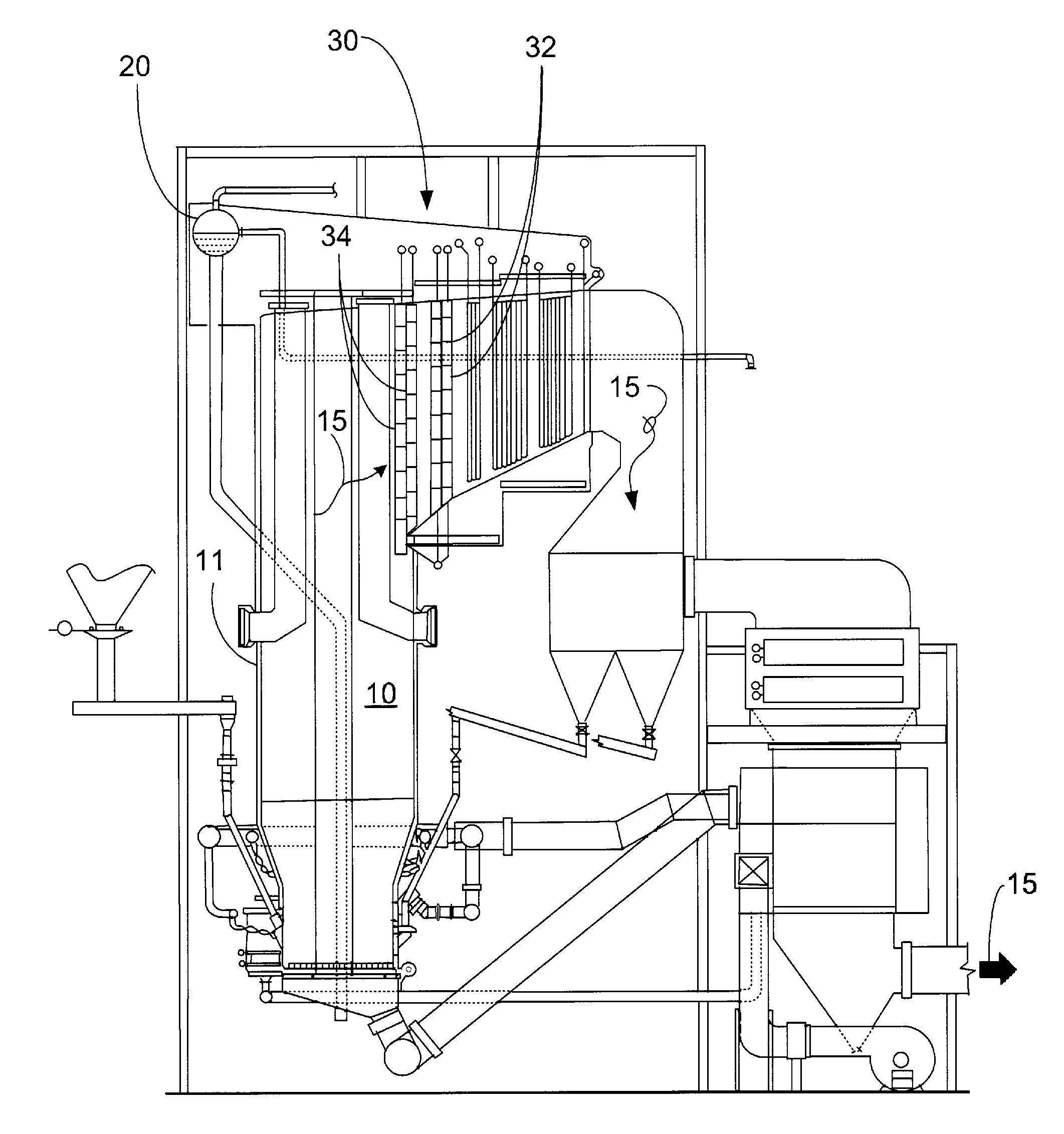
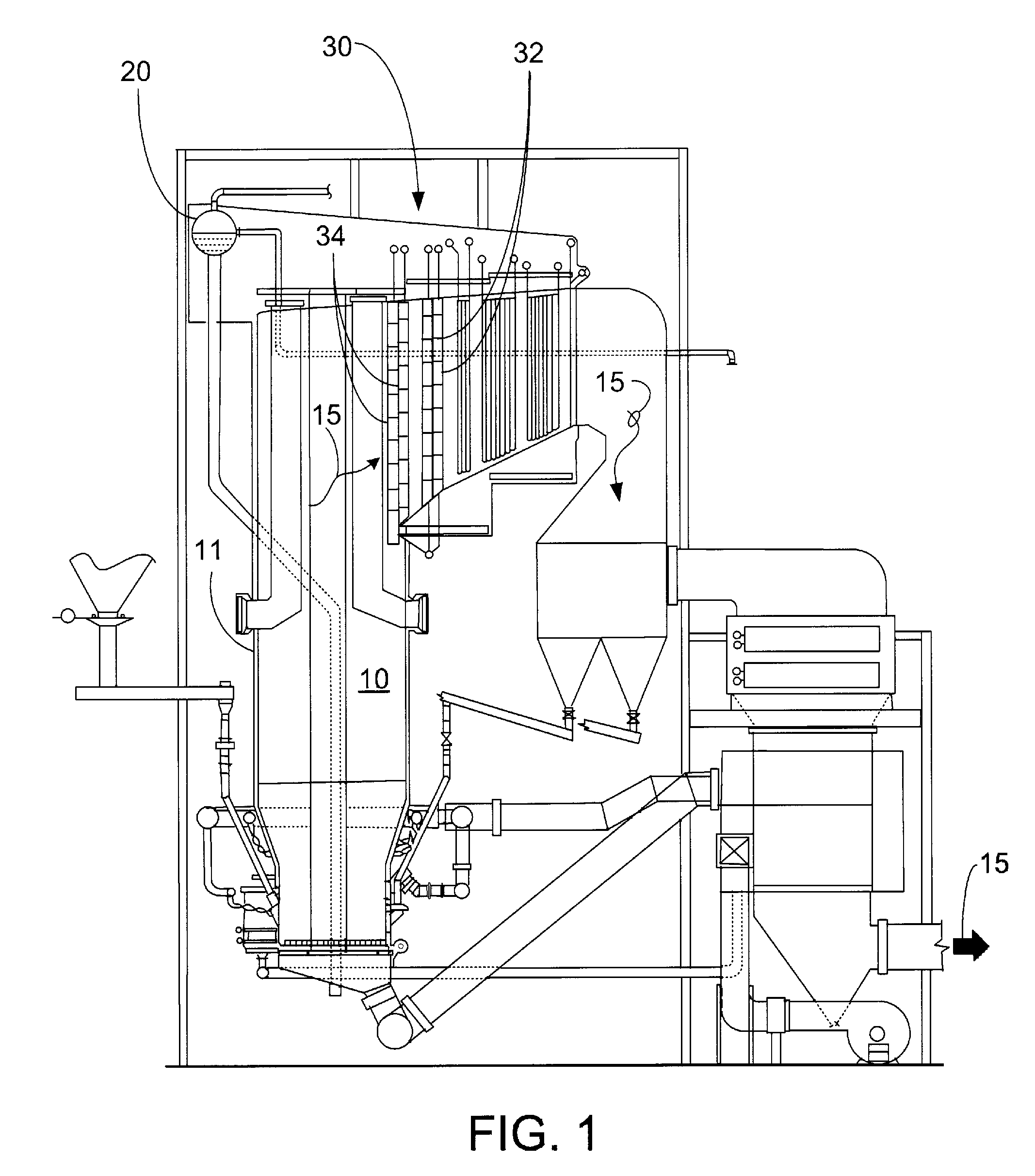
[0024]The general purpose for black plant procedures and equipment is to allow the boiler pressure to decay and the boiler setting to cool down to stable conditions as quickly as practical, without allowing water level to drop below the furnace roof, following a black plant trip. The following provides general background information and outlines of how the present invention would be applied to deal with a black plant condition, and particularly as applied to a CFB boiler arrangement experiencing a black plant condition.

[0025]Referring now to FIGS. 3 and 4, the U-beams are impact type separators which collect and recycle solids back to the furnace 10. The impact type separators serve to protect downstream heating surfaces, such as primary superheater 41, secondary superheater 42 and reheat surfaces from erosion. Attemperator 46 is an apparatus for reducing and controlling the temperature of a superheated fluid passing through it. This is accomplished by spraying high purity water 44 ...


PUM

PropertyMeasurementUnit
temperatureaaaaaaaaaa
elevationsaaaaaaaaaa

Abstract

A system and method for quickly cooling and de-pressurizing a boiler arrangement in the event of a plant power loss, a.k.a. a black plant condition. A steam discharge system injects steam from the steam / water circuit into the furnace, thereby both cooling components of the boiler arrangement and reducing pressure in the steam / water circuit. This reduces or eliminates the additional cost associated with providing extra capacity in a steam drum and / or an independently powered boiler water pump. The system and method is particularly useful for quickly cooling the U-beams of a circulating fluidized bed (CFB) boiler during a black plant condition. In application to boiler arrangements with a selective non-catalytic reduction (SNCR) system employing steam as a carrier for a NOx reducing agent, the steam discharge system advantageously uses the discharge nozzles of the SNCR system to inject the steam into the furnace.

Description

CROSS-REFERENCE TO RELATED APPLICATION[0001]Priority is claimed to U.S. provisional patent application 60 / 952,390, filed Jul. 27, 2007, the entire disclosure of which is incorporated herein by reference.FIELD AND BACKGROUND OF INVENTION[0002]The present invention relates, in general, to circulating fluidized bed (CFB) boiler arrangements and, more particularly, to a CFB boiler arrangement having a selective non-catalytic reduction (SNCR) system employed downstream of the CFB boiler furnace to achieve enhanced NOx reduction capability.[0003]CFB boiler arrangements are known and used in the production of steam for industrial processes and / or electric power generation. See, for example, U.S. Pat. Nos. 5,799,593, 4,992,085, and 4,891,052 to Belin et al.; U.S. Pat. No. 5,809,940 to James et al.; U.S. Pat. Nos. 5,378,253 and 5,435,820 to Daum et al.; and U.S. Pat. No. 5,343,830 to Alexander et al. In a CFB boiler furnace, reacting and non-reacting solids are entrained within the furnace e...

Claims


Application Information

Patent Timeline
Patent Type & Authority Applications(United States)
IPC IPC(8): F22B33/00
CPCF22B37/42F23J2219/10F23C10/10
Inventor MARYAMCHIK, MIKHAILSZMANIA, MICHAEL J.WALKER, DAVID J.WIETZKE, DONALD L.
Owner THE BABCOCK & WILCOX CO
Why Eureka
Try Eureka