
Multi-Hole Injector, in-Cylinder Gasoline Injection Type Internal Combustion Engine and Control Method for the Engine

a technology of gasoline injection and injector, which is applied in the direction of combustion engines, fuel injection apparatus, charge feed systems, etc., can solve the problems of reducing the output of the engine, cylinder liner wear, and the curved surface radius of the nozzle hole's inlet requires a high machining accuracy, so as to reduce suppress the amount of fuel, and the effect of large effective flow path area

Inactive Publication Date: 2009-01-29
HITACHI LTD
View PDF10 Cites 49 Cited by
  • Summary
  • Abstract
  • Description
  • Claims
  • Application Information

AI Technical Summary

Benefits of technology

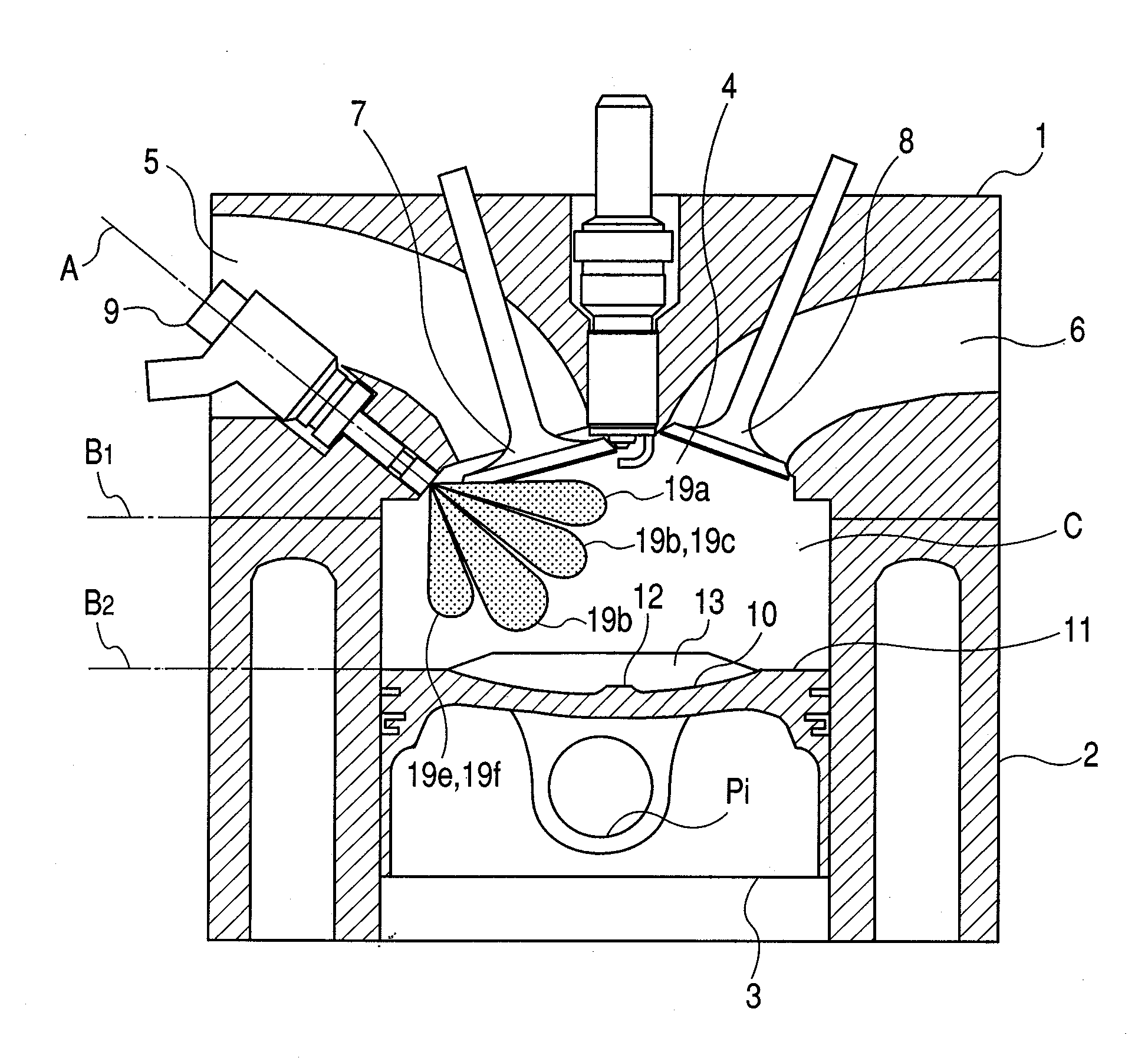
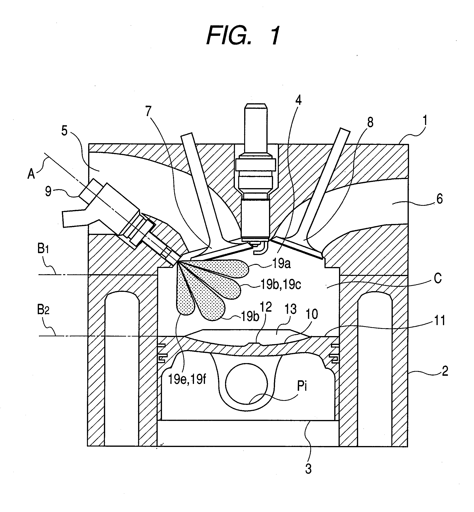
[0010]According to one aspect of the present invention described above, in connection with the flow of fuel into each nozzle hole and a fuel inflow angle (inlet angle) which are determined by a nozzle hole axis, the fuel inflow angle of a nozzle hole directed toward the central area of the piston crown or the vicinity thereof can be set small to make an effective flow path area large. Thereby, it is eventually possible to suppress the amount of fuel in the nozzle hole directed to the spark plug, and also at the time of injection in the intake stroke after warm-up, the spray of fuel does not adhere to the cylinder liner. Thus, the conventional problem could be solved.
[0011]According to another aspect of the present invention described above, in connection with the flow of fuel into each nozzle hole and a fuel inflow angle which is determined by a nozzle hole axis, the fuel inflow angle of a nozzle hole directed to the spark plug can be set large to make an effective flow path area of the nozzle orifice small. Thereby, it is possible to decrease the amount of fuel, and also at the time of injection in the intake stroke after warm-up, the spray of fuel does not adhere to the cylinder liner. Thus, the conventional problem could be solved.

Problems solved by technology

Besides, the cylinder liner may become worn due to the dilution of oil.
Further, smoke may occur in the cylinder due to the adhesion of fuel to the cylinder and piston, consequently deterioration of engine emissions and vaporization of fuel may occur, and may result in lowering of output of the engine.
However, the curved surface radius of the nozzle hole's inlet requires a high machining accuracy because the size of the nozzle hole is very small.
Besides, the required amount of fuel and the actual amount thereof may be different from each other under the influence of a machining error and thus mass production is difficult.
However, the larger the nozzle hole-diameter, the more a particle diameter of the fuel spray may become large and the combustion performance may be lowered.

Method used


Image

  • Multi-Hole Injector, in-Cylinder Gasoline Injection Type Internal Combustion Engine and Control Method for the Engine
  • Multi-Hole Injector, in-Cylinder Gasoline Injection Type Internal Combustion Engine and Control Method for the Engine
  • Multi-Hole Injector, in-Cylinder Gasoline Injection Type Internal Combustion Engine and Control Method for the Engine

Examples


first embodiment

[0103]An in-cylinder injection type engine provided with an injector having a plurality of nozzle holes, and a control unit for the engine, characterized by:

[0104]the injector provided at a tip thereof with a plate having a plurality of nozzle holes and installed on an intake side of a combustion chamber;

[0105]a spark plug installed in a central upper position of the combustion chamber;

[0106]at least one of the nozzle holes formed in the plate and directed to the spark plug;

[0107]at least one of the nozzle holes directed to a piston side with respect to the nozzle hole directed to the spark plug on the same plane as the spark plug and the injector;

[0108]at least two of the nozzle holes directed to an outer periphery portion of the piston on an intake side;

[0109]at least two of the nozzle holes are directed within a directional range of the nozzle holes on the piston side with respect to the nozzle hole directed to the spark plug and on the spark plug side with respect to the nozzle ...

second embodiment

[0111]An in-cylinder injection type engine provided with an injector having a plurality of nozzle holes, as well as a control unit for the engine, according to the first embodiment, wherein the angle between each of the nozzle holes directed to the outer periphery portion of the piston on the intake side and the tapered surface of the surface is larger than the angle between the nozzle hole directed to the piston and the tapered surface of the plate surface.

third embodiment

[0112]An in-cylinder injection type engine provided with an injector having a plurality of nozzle holes, as well as a control unit for the engine, according to the first embodiment, wherein when the injector is seen from the upstream side of the fuel flow path formed in the interior of the injector, the following structure is characterized that: at least one nozzle (A) of orifices is directed toward the piston side with respect to a nozzle hole directed toward the sparkplug side, and is directed toward the spark plug with respect to a nozzle hole directed toward the piston side, and is directed within the directional range of nozzle holes directed toward the outer periphery of the piston; an angle between the nozzle hole (A) and the tapered surface of the plate is larger than an angle between the nozzle hole directed to the spark plug and the tapered surface of the plate.


PUM


Abstract

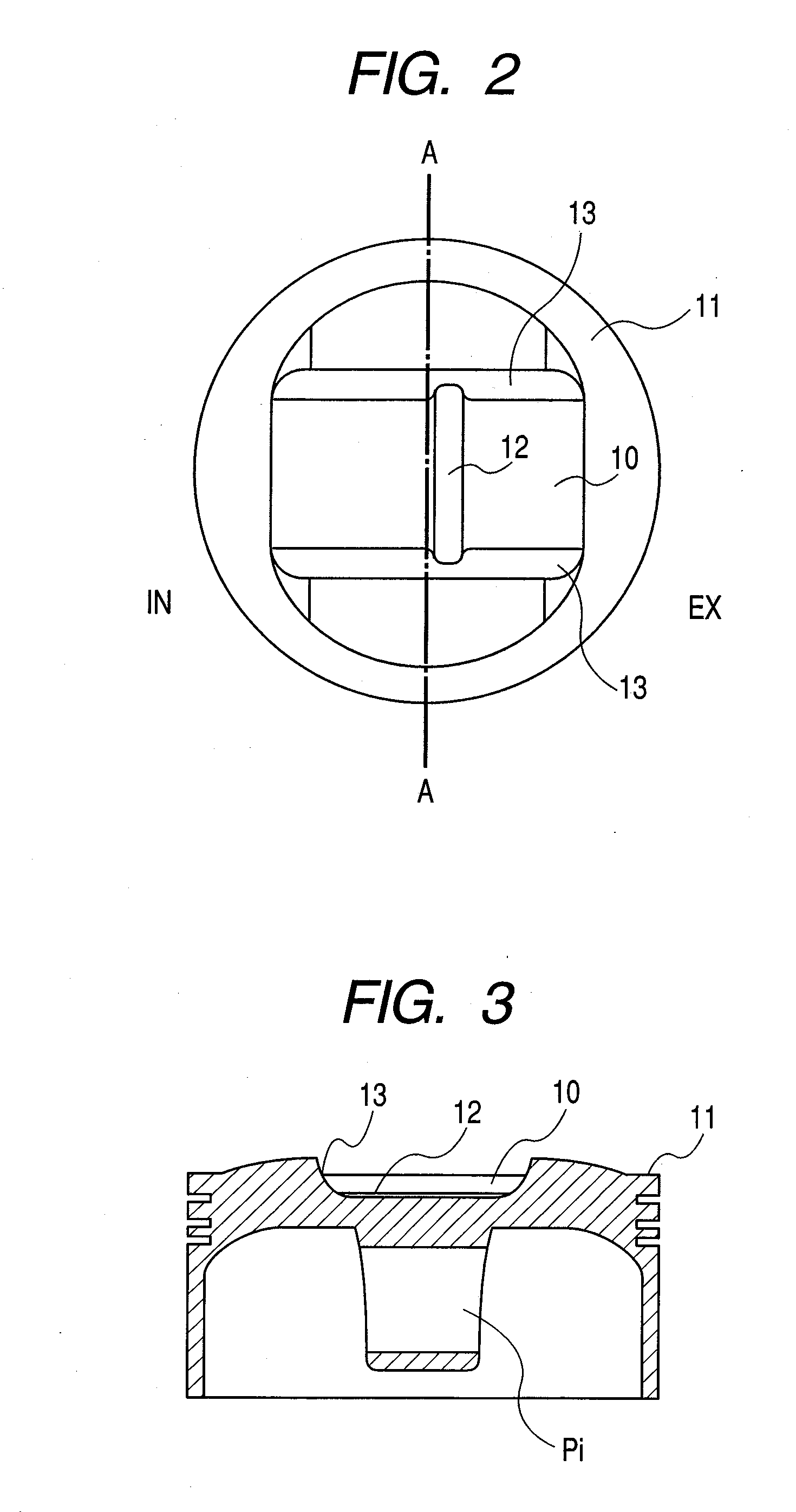
Improvement of combustion stability in retard ignition at the time of starting in a cold state, high output in a full throttle condition, reduction of smoke, and prevention of wear of the cylinder liner caused by oil dilution, are to be attained. In connection with the flow of fuel into each hole and a fuel inflow angle which is determined by the axis of each hole formed in a plate, the fuel inflow angle of an hole directed to a spark plug is set large to reduce an effective flow path area, thereby making the amount of fuel in the hole smaller than in other holes. A shallow cavity is formed in a piston crown face and a small prominence confronting fuel sprays is formed within the cavity.

Description

CLAIM OF PRIORITY[0001]The present application claims priority from Japanese patent application serial no. 2007-191534 filed on Jul. 24, 2007, the contents of which are hereby incorporated by reference into this application.FIELD OF THE INVENTION[0002]The present invention relates to a multi-hole injector having a plurality of nozzle holes, in-cylinder gasoline injection (direct gasoline injection) type internal combustion engine having the multi-hole injector, and a method for controlling the engine.BACKGROUND OF THE INVENTION[0003]In a conventional in-cylinder gasoline injection type internal combustion engine provided with multi-hole injector, for example in Japanese Patent Laid-Open Publication No. 2005-139989, it is proposed that nozzle holes in the injector vary in radius of a curved surface of each nozzle hole's inlet portion so that penetrations of fuel sprays from the nozzle holes vary in penetration.[0004]For an in-cylinder gasoline injection type internal combustion engin...

Claims


Application Information

Patent Timeline
IPC IPC(8): F02B3/00
CPCF02B17/005F02B23/104F02B2023/103F02B2023/106F02B2075/125Y02T10/123F02M61/14F02M61/1813F02M61/1846Y02T10/125F02B2275/48Y02T10/12
Inventor KIHARA, YUSUKESUKEGAWA, YOSHIHIROTSUCHITA, KENJITSUCHITA, SUMIEFUJII, HIROSHISEKINE, ATSUSHI
Owner HITACHI LTD
Learn More